Chucking device and chucking method
a chucking device and chucking technology, applied in the direction of gripping heads, pipe joints, sleeves/socket joints, etc., can solve the problem of vacuum sucking of substrate warpage, achieve reliable chucking of substrate, prevent contamination due to warpage, and reduce the effect of warpag
- Summary
- Abstract
- Description
- Claims
- Application Information
AI Technical Summary
Benefits of technology
Problems solved by technology
Method used
Image
Examples
first embodiment
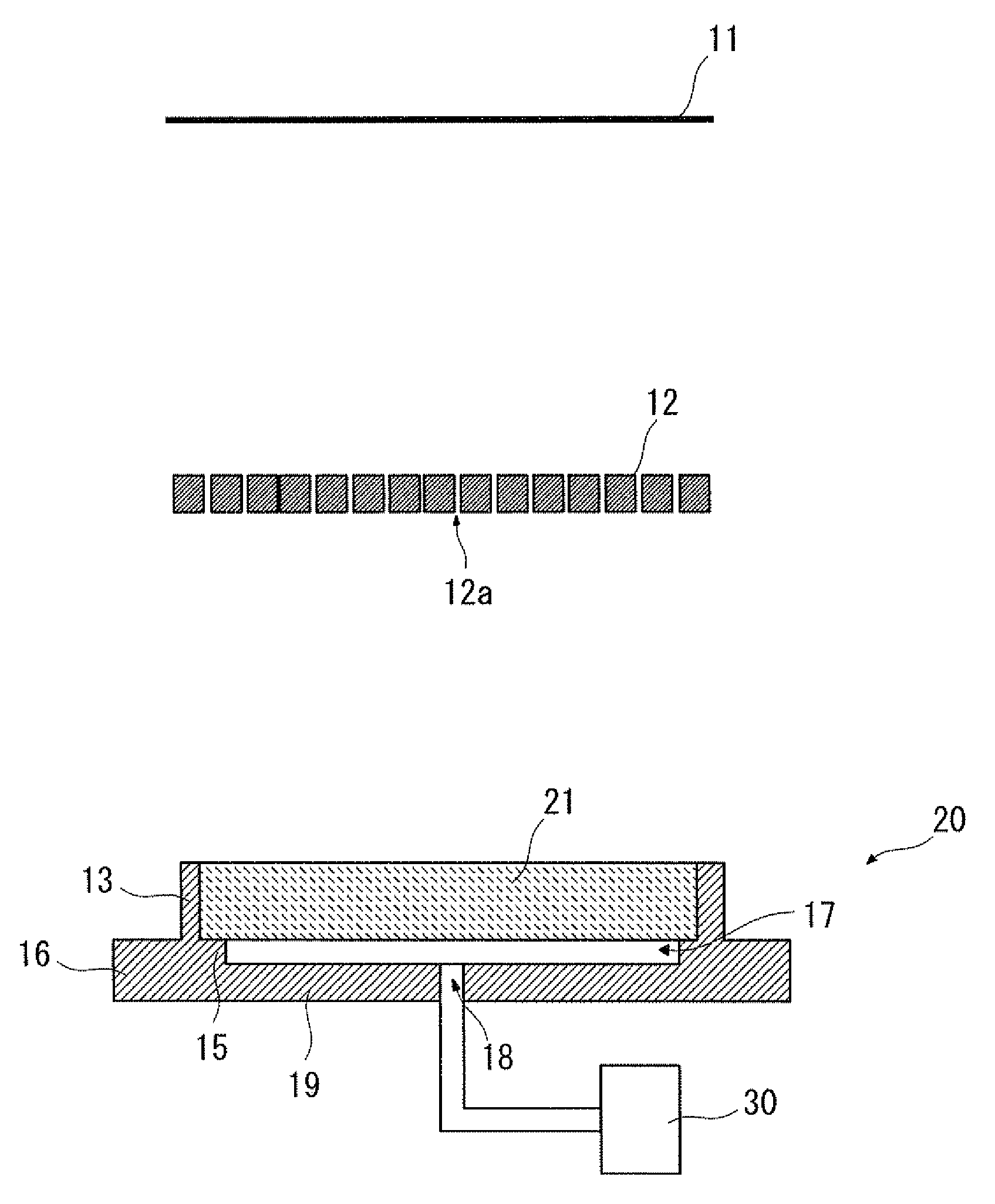
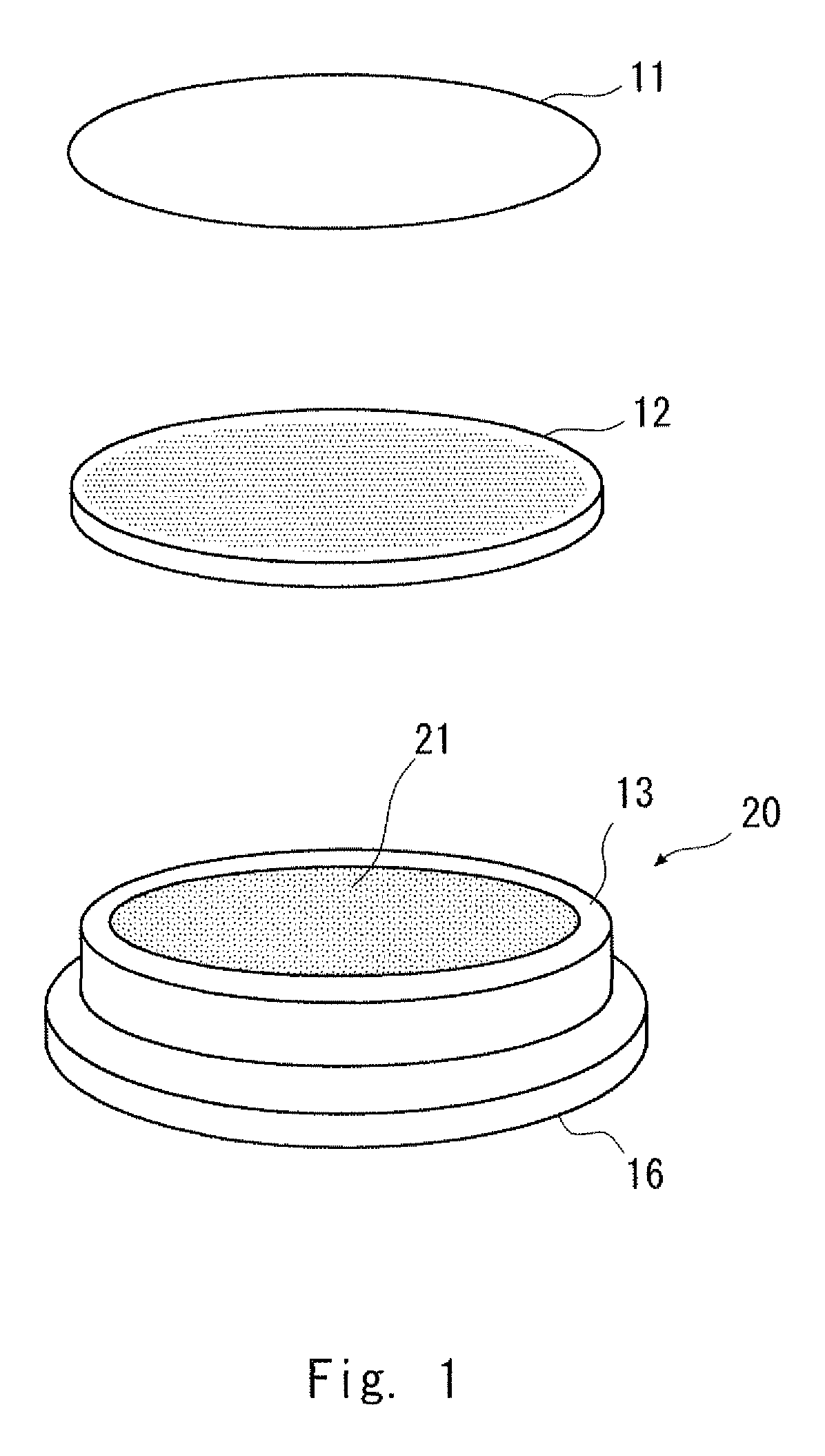
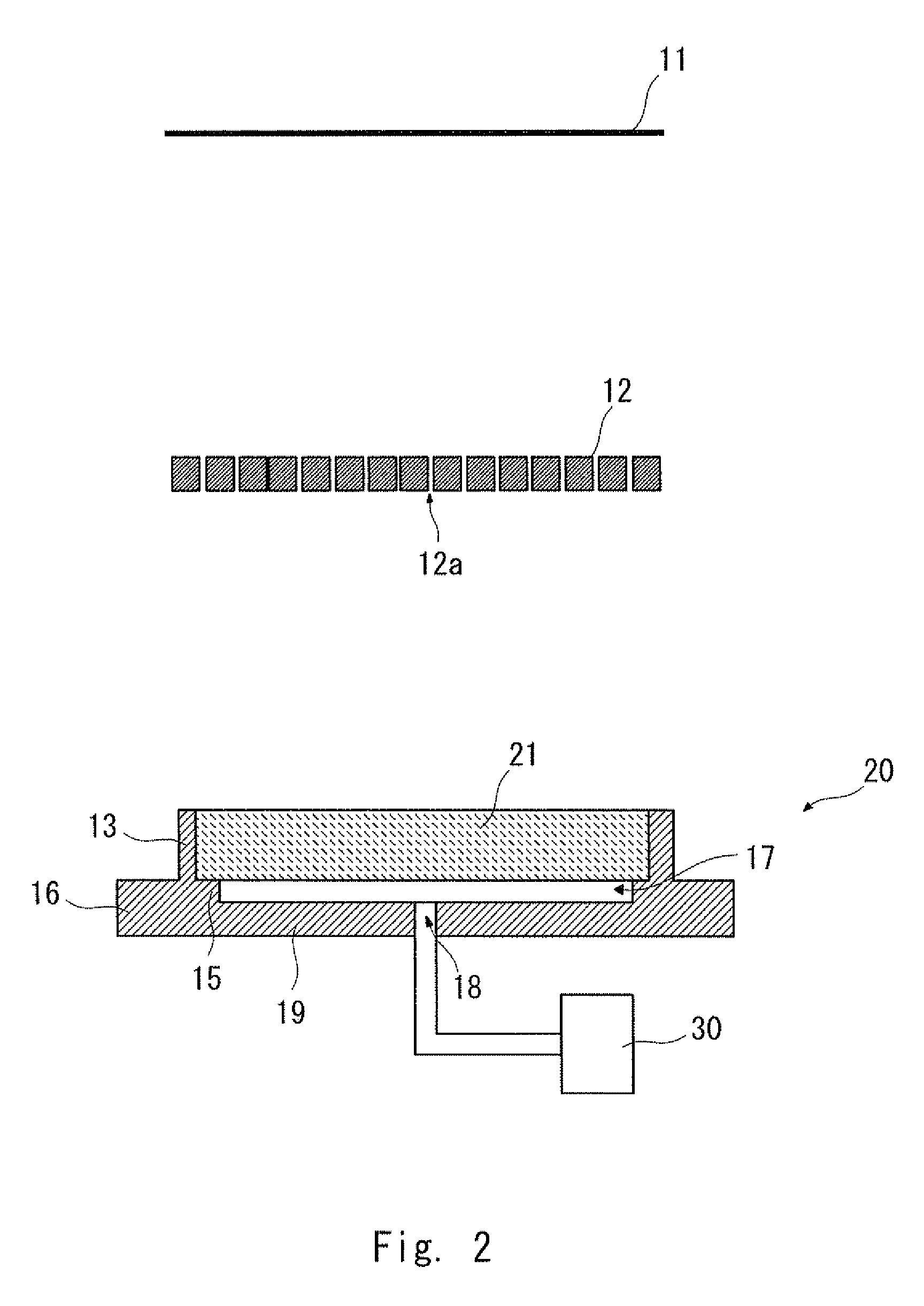
[0030]A chucking device and a chucking method according to a first embodiment will be described with reference to FIGS. 1 and 2. FIG. 1 is a perspective view for explaining each component of the chucking device. FIG. 2 is a sectional view schematically showing each component of the chucking device. FIGS. 1 and 2 illustrate that the members are spaced apart as needed. As shown in FIGS. 1 and 2, in order to vacuum-suck a substrate, such as a wafer 11, the chucking device includes a perforated plate 12, a support portion 20, and a vacuum pump 30.
[0031]The wafer 11 is, for example, a silicon wafer, which is a flat plate. The wafer 11 is disposed on the perforated plate 12. The perforated plate 12 is a first plate having a plurality of through-holes 12a formed therein. In other words, the perforated plate 12 is a perforated plate having the through-holes 12a. The perforated plate 12 is a flat plate and has a disk shape corresponding to the wafer 11. The through-holes 12a penetrate from a...
second embodiment
[0046]A second embodiment will be described with reference to FIGS. 5 and 6. FIG. 5 is a perspective view for explaining each component of a chucking device. FIG. 6 is a sectional view schematically showing each component of the chucking device. FIGS. 5 and 6 illustrate that the members are spaced apart as needed. As shown in FIGS. 5 and 6, in order to vacuum-suck a substrate, such as the wafer 11, the chucking device includes the perforated plate 12, a sheet member 31, a support plate 32, the support portion 20, and the vacuum pump 30. That is, the sheet member 31 and the support plate 32 are provided instead of the porous plate 21 of the first embodiment. Note that the description of the same components as those of the first embodiment will be omitted.
[0047]The support plate 32, which is a second plate, supports the sheet member 31, the perforated plate 12, and the wafer 11. The sheet member 31 is disposed between the support plate 32 and the perforated plate 12. In other words, t...
PUM
| Property | Measurement | Unit |
|---|---|---|
| thickness | aaaaa | aaaaa |
| depth | aaaaa | aaaaa |
| size | aaaaa | aaaaa |
Abstract
Description
Claims
Application Information
 - R&D
- Intellectual Property
- Life Sciences
- Materials
- Tech Scout
- Unparalleled Data Quality
- Higher Quality Content
- 60% Fewer Hallucinations
Browse by: Latest US Patents, China's latest patents, Technical Efficacy Thesaurus, Application Domain, Technology Topic, Popular Technical Reports.
© 2025 PatSnap. All rights reserved.Legal|Privacy policy|Modern Slavery Act Transparency Statement|Sitemap|About US| Contact US: help@patsnap.com


