
Resistive thin layer heating of fluorescent lamp

a technology of fluorescent lamps and thin layers, applied in the field of resistive thin layer heating of fluorescent lamps, can solve the problems of not providing an instant light feature, not providing an efficient and effective way for warming up the mercury source, and relatively long run-up time of fluorescent lamps,

Inactive Publication Date: 2015-08-25
GENERAL ELECTRIC CO
View PDF20 Cites 1 Cited by
  • Summary
  • Abstract
  • Description
  • Claims
  • Application Information

AI Technical Summary

Benefits of technology

The patent text describes the technical effects and advantages of the invention. In simple terms, the invention has various aspects and advantages that can be easily understood and implemented. These aspects include improvements in operational efficiency, cost savings, and optimized performance. These technical effects can benefit various industries and applications, making the invention highly adaptable and flexible. Overall, the invention provides a solution to challenges and problems faced by various industries and offers a wide range of benefits to optimize performance and improve overall efficiency.

Problems solved by technology

However, one of the main disadvantages of FLs, including CFLs, is their relatively long run-up time.
However, one disadvantage of this proposed solution is that it does not provide an instant light feature.
Although it has been suggested to simultaneously turn on both lamps in order to result in instant light from the incandescent lamp, and then subsequently terminate or switch off the incandescent lamp, these known arrangements do not provide an efficient and effective manner for warming up the mercury source.
This arrangement does not provide an accurate assessment of the actual thermal conditions of the discharge vessel.
Further, locating a thermally sensitive element in a ballast compartment is potentially impacted by temperature variations caused by different illumination positions of the lamp e.g. vertically upright or inverted.
As a result, the thermally sensitive element does not provide an accurate representation of the heat conditions.
The thermal switch associated with this arrangement aids in starting of the fluorescent lamp in low temperature, ambient conditions; however, it does not improve run-up of the lamp assembly.
Unfortunately, due to the SCR, the RMS value of the input power is about 70% of the nominal value and results in a specialized incandescent lamp that has increased cost and complexity.

Method used


Image

  • Resistive thin layer heating of fluorescent lamp
  • Resistive thin layer heating of fluorescent lamp
  • Resistive thin layer heating of fluorescent lamp

Examples


Embodiment Construction

[0024]Reference will now be made in detail to present embodiments of the invention, one or more examples of which are illustrated in the accompanying drawings.

[0025]Each example is provided by way of explanation of the invention, not limitation of the invention. In fact, it will be apparent to those skilled in the art that modifications and variations can be made in the present invention without departing from the scope or spirit thereof. For instance, features illustrated or described as part of one embodiment may be used on another embodiment to yield a still further embodiment. Thus, it is intended that the present invention covers such modifications and variations as come within the scope of the appended claims and their equivalents.

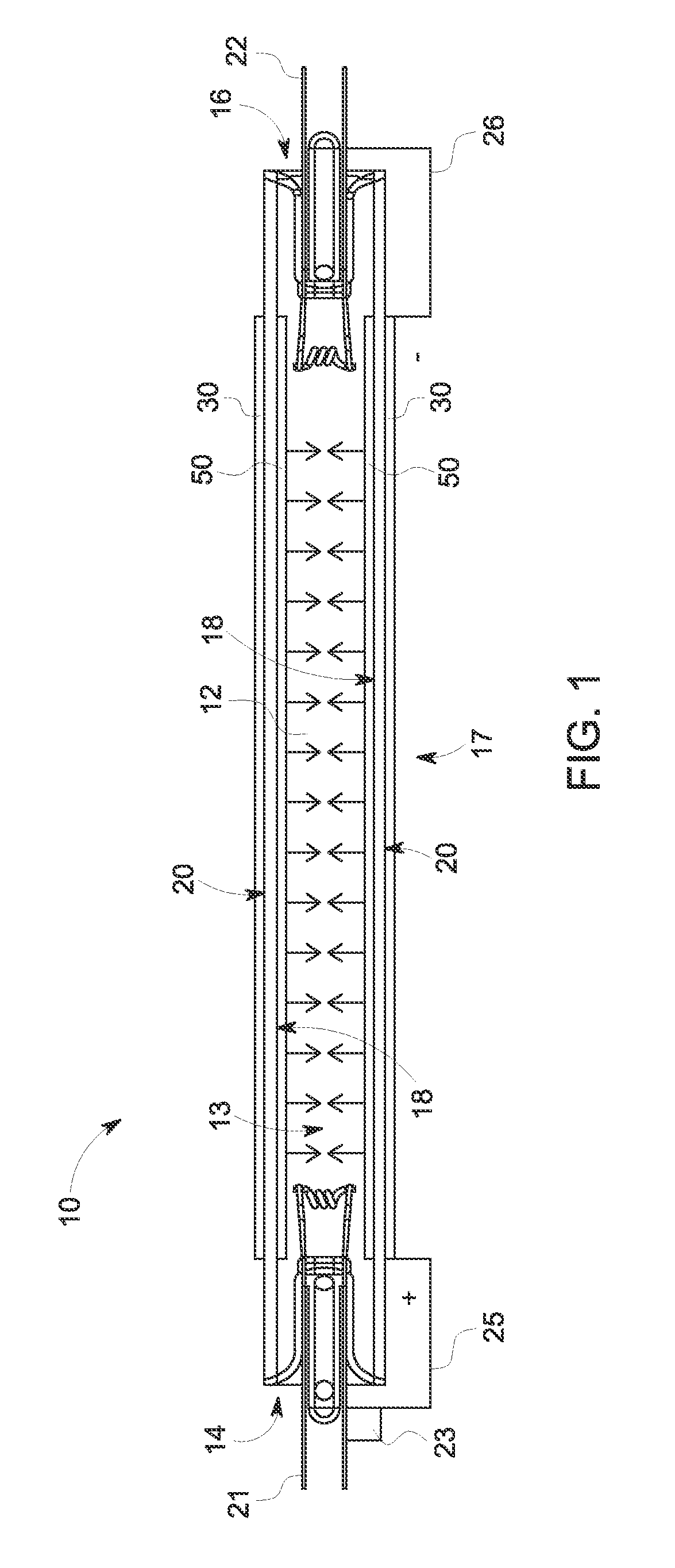
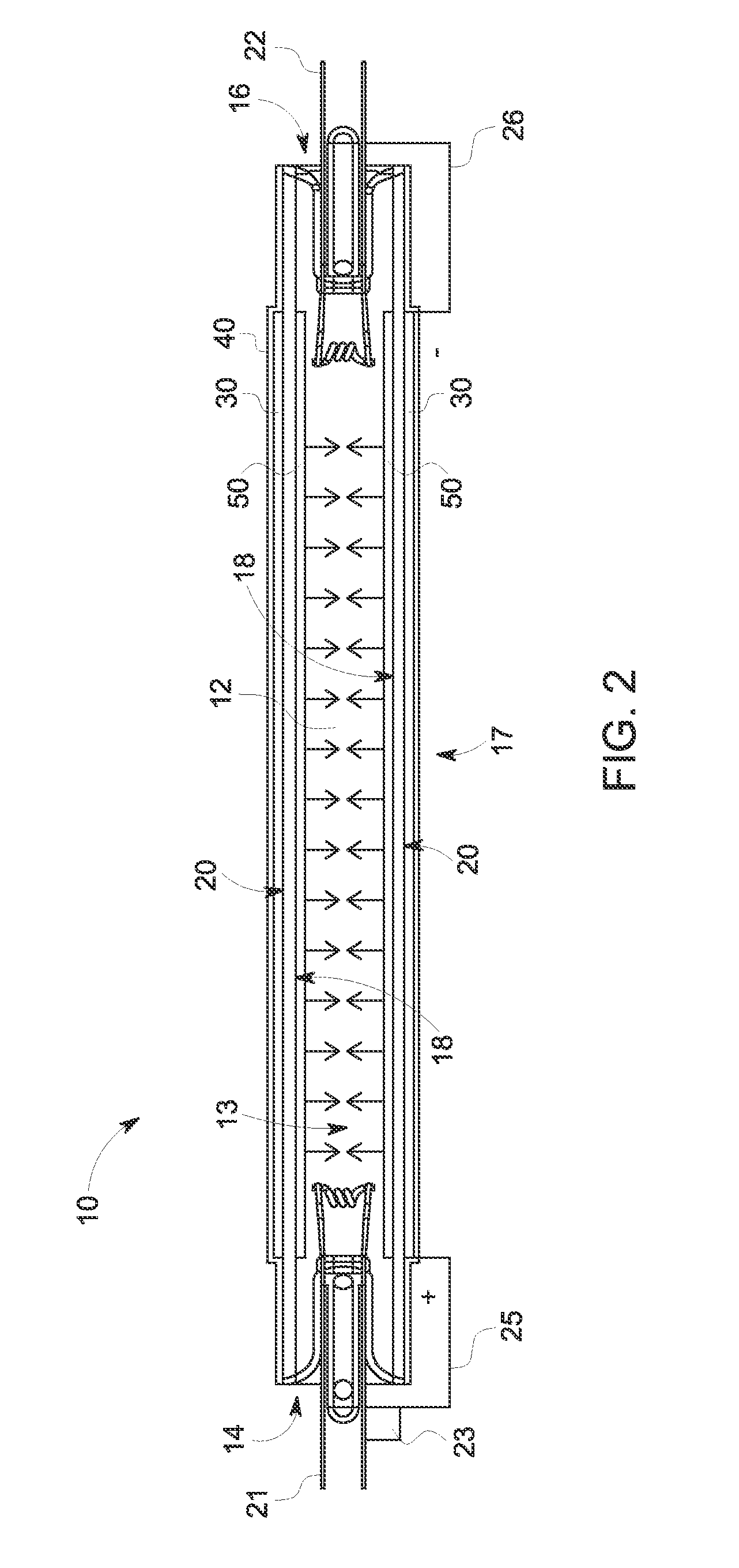
[0026]Fluorescent lamps (FLs) having improved properties, including compact fluorescent lamps, are generally provided, along with their methods of manufacture. Referring to FIG. 1, an exemplary fluorescent lamp 10 is shown including a discharge tube ...


PUM


Abstract

Fluorescent lamps, along with their methods of manufacture and use, are provided. The fluorescent lamp can include a discharge tube extending from a first end to a second end; a resistive transparent coating (e.g., a tin oxide thin film layer, such as a fluor-doped tin oxide thin film layer) on the outer surface of the discharge tube; and a pair of electric terminals positioned on the discharge tube such that a first terminal is on the first end and a second terminal is on the second end.

Description

FIELD OF THE INVENTION[0001]Embodiments of the present invention generally involve lighting or lamp assemblies and more particularly to a fluorescent lamp (FL) or lamp assembly having improved run-up properties.BACKGROUND OF THE INVENTION[0002]The majority of the known and commercially available low-pressure fluorescent discharge lamps are so-called fluorescent lamps (FLs) at present. For example, compact fluorescent lamps (CFLs) are intended to replace incandescent lamps used in a wide field of industry and home applications. In order to provide a CFL that resembles conventional incandescent lamps, a bulb shaped outer envelope may encapsulate the CFLs. The advantages of these lamps are low power consumption and long lifetime. However, one of the main disadvantages of FLs, including CFLs, is their relatively long run-up time.[0003]A number of different solutions currently exist to improve run-up behavior, i.e., the time needed after switching on the supply for the lamp to reach 80% ...

Claims


Application Information

Patent Timeline
Patent Type & Authority Patents(United States)
IPC IPC(8): H01J61/35H01J9/20H01J61/04H01J65/04H01J61/28H01J61/54H01J61/52H01J61/56H01J19/36
CPCH01J61/28H01J61/35H01J61/523H01J61/54H01J19/36
Inventor CSIBI, LAJOSBANKUTI, LASZLOKORONYA, CSABAKALLAY, JANOSALMOSDI, PETER
Owner GENERAL ELECTRIC CO
Learn More