
Calibratable magnetic field sensor and method of producing same

a magnetic field sensor and calibration method technology, applied in the direction of magnetic field measurement using galvano-magnetic devices, magnitude/direction of magnetic fields, measurement devices, etc., can solve the problem of inaccurate calibration of magnetic field sensors, the sensitivity of vertical hall sensor elements can be determined with a relatively low level of accuracy, and the individual layer structure is subject to process variations. the effect of reducing influen

Active Publication Date: 2015-08-25
FRAUNHOFER GESELLSCHAFT ZUR FOERDERUNG DER ANGEWANDTEN FORSCHUNG EV
View PDF4 Cites 22 Cited by
  • Summary
  • Abstract
  • Description
  • Claims
  • Application Information

AI Technical Summary

Benefits of technology

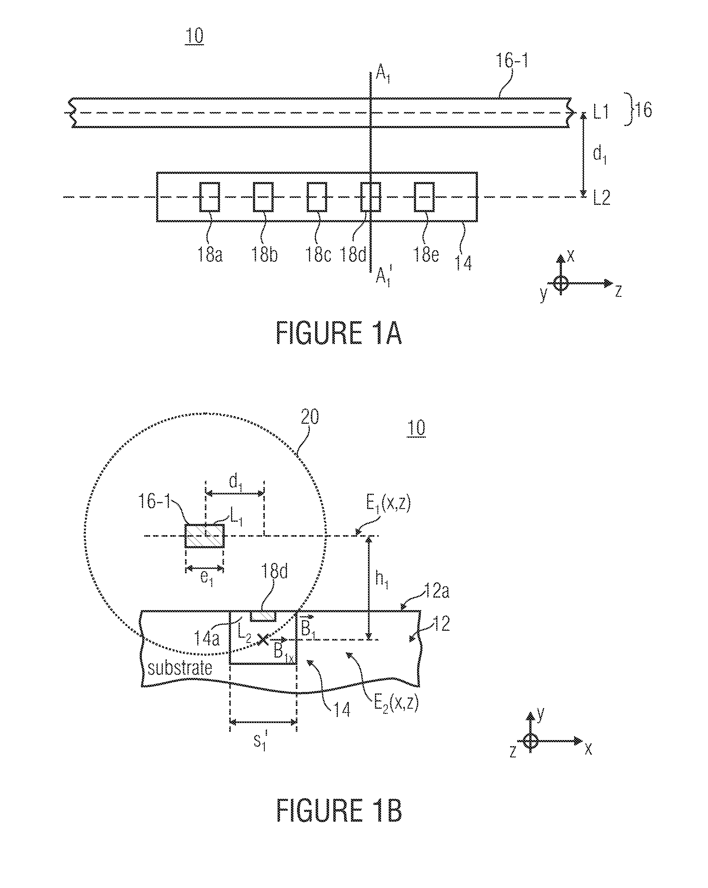
[0013]It is the core idea of the present invention that an exciting conductor arrangement comprising an exciting conductor or a plurality of exciting conductors be arranged in a magnetic field sensor, or a calibratable magnetic field sensor arrangement so as to be laterally offset from a central position located perpendicularly above or below the vertical Hall sensor element, said offset or lateral distance from the central position being set, in dependence on the vertical distance, such that process variations due to manufacturing will have a clearly reduced influence on a calibration process without the actually occurring process variations having to be known in terms of quantity. Due to the lateral offset of the exciting conductor from the central position, the component B1x, which may be detected by the Hall sensor element, in the x direction of the magnetic flux density within the active semiconductor area of the Hall sensor element will have a curve, in dependence on the vertical distance and / or the height between the exciting conductor and the active area of the Hall sensor element, which has a local maximum and thus exhibits, in the area around the local maximum, a very small dependence of the magnetic flux density on process-induced variations in the distance.

Problems solved by technology

With exciting (excitation) coils or exciting conductor patterns, the problem may arise that during manufacturing of the magnetic field sensor in a semiconductor substrate, the individual layer structures are subjected to process variations as typically occur in the manufacturing of semiconductor devices.
Since in the calibration of the magnetic field sensor by means of a magnetic field created by a defined calibration current, the position and / or the effective distance of the exciting line from the active area of the Hall sensor element is accounted for, any process tolerances not taken into account may lead to inaccurate calibration of the magnetic field sensor.
As a result, the sensitivity of vertical Hall sensor elements can be determined with a relatively low level of accuracy only.

Method used


Image

  • Calibratable magnetic field sensor and method of producing same
  • Calibratable magnetic field sensor and method of producing same
  • Calibratable magnetic field sensor and method of producing same

Examples


Embodiment Construction

[0026]Before the present invention will be explained in more detail with reference to the drawings, it shall be noted that elements that are identical or identical in terms of function or effect are provided with identical reference numerals in the figures, so that the descriptions of said elements represented in different embodiments are mutually exchangeable and / or mutually applicable.

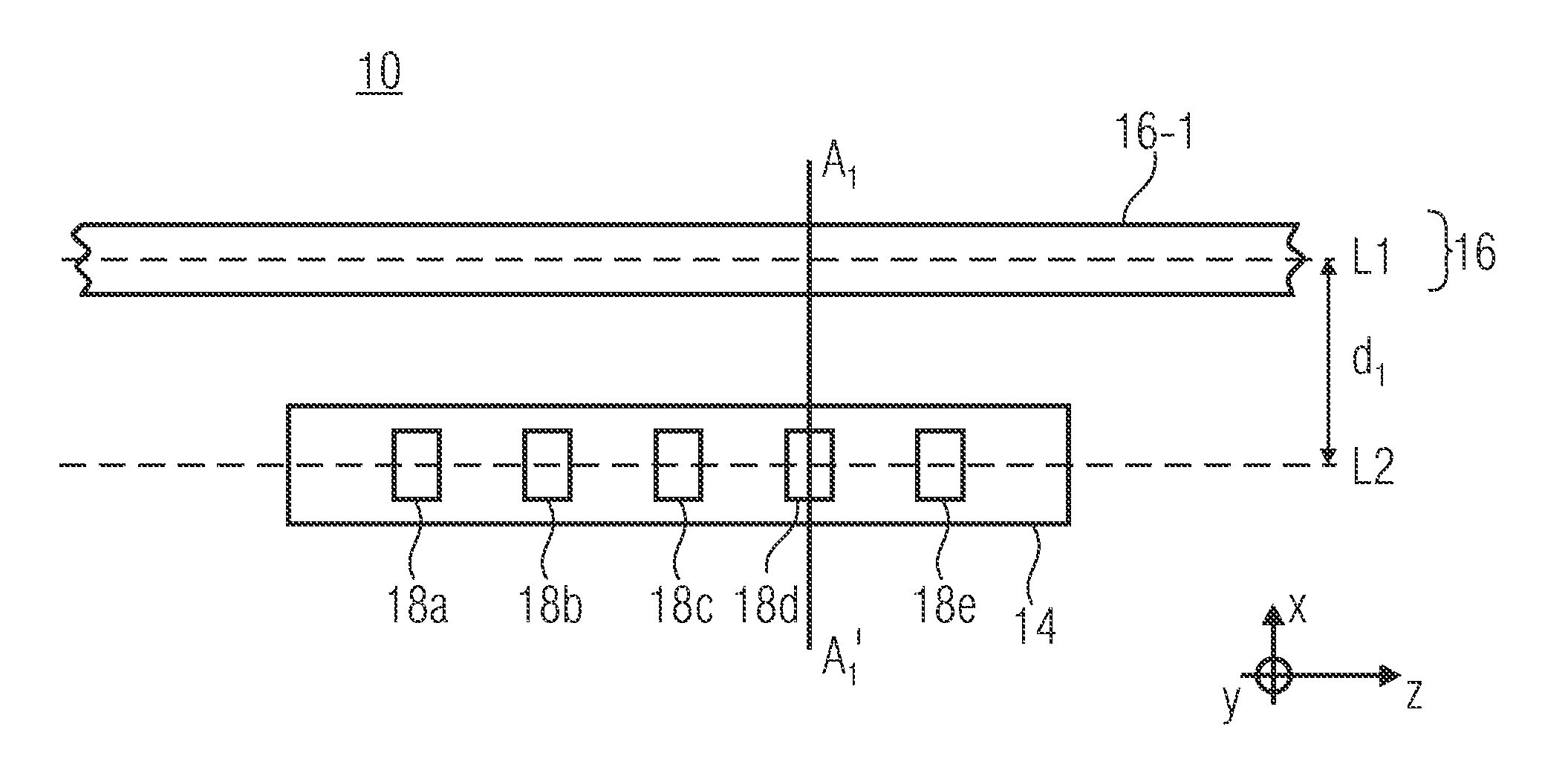
[0027]A first embodiment of a calibratable magnetic field sensor 10 in accordance with the present invention will be described by means of FIGS. 1a-b.

[0028]FIGS. 1a-b show, in a schematic sectional representation, the calibratable magnetic field sensor 10 comprising the vertical Hall sensor element 14 arranged within a semiconductor substrate 12, and the exciting conductor arrangement 16 spaced apart from the Hall sensor element 14. In the embodiment depicted in FIGS. 1a-b, the exciting conductor arrangement 16 comprises an exciting conductor 16-1. As is further depicted in FIGS. 1a-b, the active ar...


PUM


Abstract

Magnetic field sensor having a vertical Hall sensor element arranged in a semiconductor substrate, and an exciting conductor arrangement having at least one exciting conductor, the exciting conductor being arranged within an exciting conductor plane which is spaced apart, in parallel to the substrate surface, from the vertical Hall sensor element at a vertical distance h1 having a tolerance range Δh1 which is due to the manufacturing process, and which exciting conductor further has a lateral distance d1 as an offset from a center position which is located, in relation to the substrate surface, perpendicularly to the vertical Hall sensor element, and the lateral distance d1 being dimensioned such that a vertical calibration component B1x of a magnetic flux density B1 created by the exciting conductor arrangement in the vertical Hall sensor element changes by less than 5% within the tolerance range Δh1 for the vertical distance h1.

Description

CROSS-REFERENCE TO RELATED APPLICATIONS[0001]This application claims priority from German Patent Application No. 102011004391.8-35, which was filed on Feb. 18, 2011 and is incorporated herein in its entirety by reference.[0002]The present invention relates to a calibratable magnetic field sensor comprising a vertical Hall sensor element, and to a method of producing same.BACKGROUND OF THE INVENTION[0003]To determine the sensitivity of a magnetic field sensor, a magnetic field having a magnetic flux density, which should be known, if possible, is created at the location of the sensor by impressing a defined current into a coil or an exciting (excitation) conductor. The resulting change in the output signal of the magnetic field sensor upon application of a calibrating magnetic field may then be used to infer the sensitivity of the sensor. Thus, in a Hall sensor element, a change in the Hall voltage, which is caused by a change in the magnetic flux density in the sensor element, may b...

Claims


Application Information

Patent Timeline
Patent Type & Authority Patents(United States)
IPC IPC(8): G01R33/07G01R33/00
CPCG01R33/0035G01R33/0017G01R33/077
Inventor STAHL-OFFERGELD, MARKUSERNST, ROLANDHOHE, HANS-PETER
Owner FRAUNHOFER GESELLSCHAFT ZUR FOERDERUNG DER ANGEWANDTEN FORSCHUNG EV
Learn More