Reduction of tool mode and drilling noise in acoustic LWD
a tool mode and noise reduction technology, applied in seismology for waterlogging, borehole/well accessories, surveys, etc., can solve the problems of affecting the noise of the tool mode can interfere with the determination of compressional and shear wave velocities, and the detection capability and efficiency of acoustic lwd are known to be affected, so as to achieve accurate prediction of tool mode and drilling noise, the effect of similar
- Summary
- Abstract
- Description
- Claims
- Application Information
AI Technical Summary
Benefits of technology
Problems solved by technology
Method used
Image
Examples
embodiment 200
[0034]In the tool embodiment 200′ depicted on FIG. 3B, the first and second transmitters 120A and 120B may advantageously be configured to transmit acoustic energy having different frequencies. For example, the first transmitter 120A may be configured to transmit an acoustic signal having a center frequency in the range from about 12 to about 16 kHz, which may be advantageously utilized to determine a formation compressional wave velocity. The second transmitter 120B may be configured to transmit an acoustic signal having a center frequency in the range from about 4 to about 8 kHz (or less), which may be advantageously utilized to determine a formation shear wave velocity.
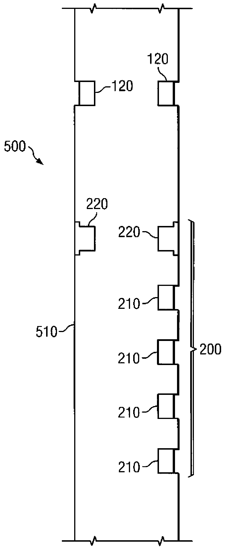
[0035]Since the tool mode arrivals and drilling noise emanate from different directions (for the upper transmitter), the tool embodiment 200′ including first and second reference receivers 220 may advantageously provide for better isolation of these noise signals. Moreover, first and second reference receivers 220 ...
embodiment 210
[0038]In the exemplary embodiment depicted on FIG. 4A, regular receivers 210 include a multi-layered device having a piezoelectric transducer element 320 interposed between a backing layer 330 and at least one impedance matching layer 315. Such multi-layered receivers are conventional in the prior art. The multi-layered structure may be deployed, for example, in a centralizer 335 so as to center the transducer element 320 in a sensor housing 310. An electrical connector 340 provides for electrical communication between transducer element 320 and a controller (not shown). The exemplary receiver embodiment 210 depicted further includes a protection layer 305 (e.g., a thin layer of titanium metal) deployed over an outer surface of the impedance matching layer 315. The protection layer is intended to provide physical protection for the receiver, for example, from cuttings in the drilling fluid and impacts with the borehole wall.
[0039]The piezoelectric transducer 320 may include substant...
PUM
 Abstract
Description
Claims
Application Information
 - R&D
- Intellectual Property
- Life Sciences
- Materials
- Tech Scout
- Unparalleled Data Quality
- Higher Quality Content
- 60% Fewer Hallucinations
Browse by: Latest US Patents, China's latest patents, Technical Efficacy Thesaurus, Application Domain, Technology Topic, Popular Technical Reports.
© 2025 PatSnap. All rights reserved.Legal|Privacy policy|Modern Slavery Act Transparency Statement|Sitemap|About US| Contact US: help@patsnap.com


