
Touch panel including each touch controller for each divided region and liquid crystal display device using the same

a touch panel and divided region technology, applied in the field of touch panels, can solve the problems of deteriorating touch sensitivity and minute motions that occur in single sensing areas that cannot be sensed, and achieve the effects of improving touch sensitivity uniformity, and improving touch resolution and resolving power

Active Publication Date: 2015-07-28
LG DISPLAY CO LTD
View PDF14 Cites 4 Cited by
  • Summary
  • Abstract
  • Description
  • Claims
  • Application Information

AI Technical Summary

Benefits of technology

[0056]First of all, in case the size of the touch panel is larger even when the touch controller (driving IC) having the limited pin number is used, the touch panel is local dimmed and independent touch controllers are provided in the divided regions respectively. A single sensing are of a sensing electrode is formed in a single touch area or less and the sensing electrodes are driven separately for the divided regions. As a result, the touch panel may be applicable to a large-sized model without deterioration of touch sensitivity.
[0057]Second, when more minute touch sensitivity is represented, the number of the touch controllers is increased to be formed in the divided regions correspondingly. As a result, touch resolution and a resolving power may be improved in a large-sized model.
[0058]Third, a routing line is further provided in the border areas and outer areas to be connected with the sensing electrodes and touch controllers. As a result, touch may be detected in the border areas and the outer areas of the panel and thus uniformity of touch sensitivity may be improved accordingly. In this case, the sensing electrodes are formed of rhombus patterns configured to connect neighboring sensing areas with the sensing electrodes, respectively. When an end of the sensing electrode is connected with the touch controller, a corresponding routing line is corresponding to a vertex of the rhombus pattern. As a result, without any change of configuration, it is possible to add the routing line.
[0059]Fourth, for example, the detection of the touch is implemented in the crossing areas of the scanning lines having voltage change generated in X-axis direction scanning lines and Y-axis direction scanning lines. Such the detection may have a ghost phenomenon sensing an area without touch as touch point in case of multi-touch is generated. However, according to the mutual capacitive type of the present invention, change of the predetermined area size is sensed and the ghost phenomenon may be prevented.
[0060]Fifth, according to the mutual capacitive type, one of X-axis and Y-axis direction electrodes is a driving voltage applying line and the other is a sensing voltage detecting line. In this case, the driving voltage applying line is located corresponding to the border area and triangle pattern electrodes in the border area are driving voltage applying lines and the other sensing voltage detecting lines are complete rhombus patterns located in all of the regions. This structure enables the electrode distance of the driving voltage applying lines to be shorter to reduce the RC time constant structurally and it enables the sensing voltage detecting lines to have uniformly maintained mutual capacitance in an initial state. As a result, in case touch is generated, the lowest vale of the mutual capacitance in a touch generating area is calculated to detect touch more precisely.

Problems solved by technology

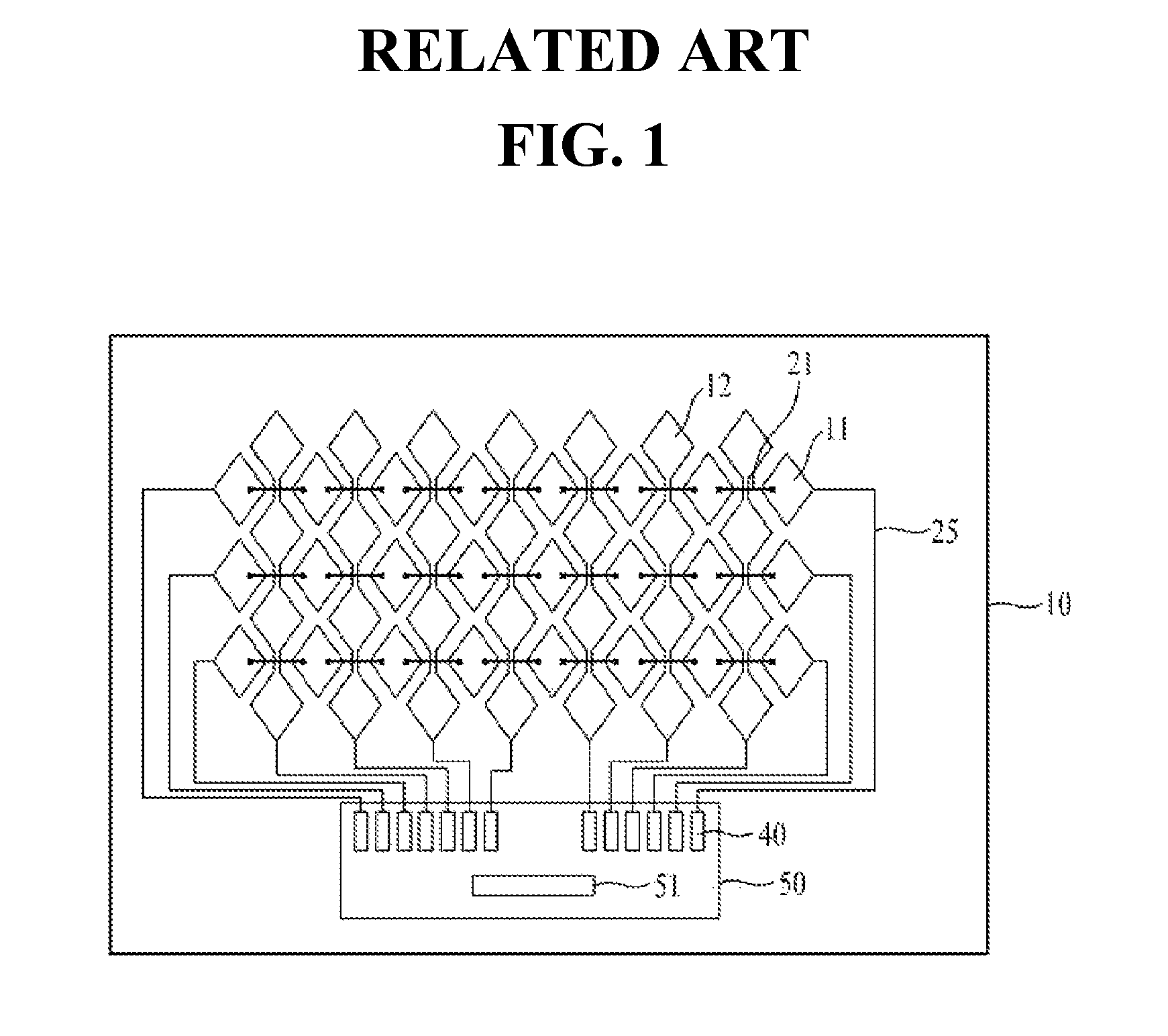
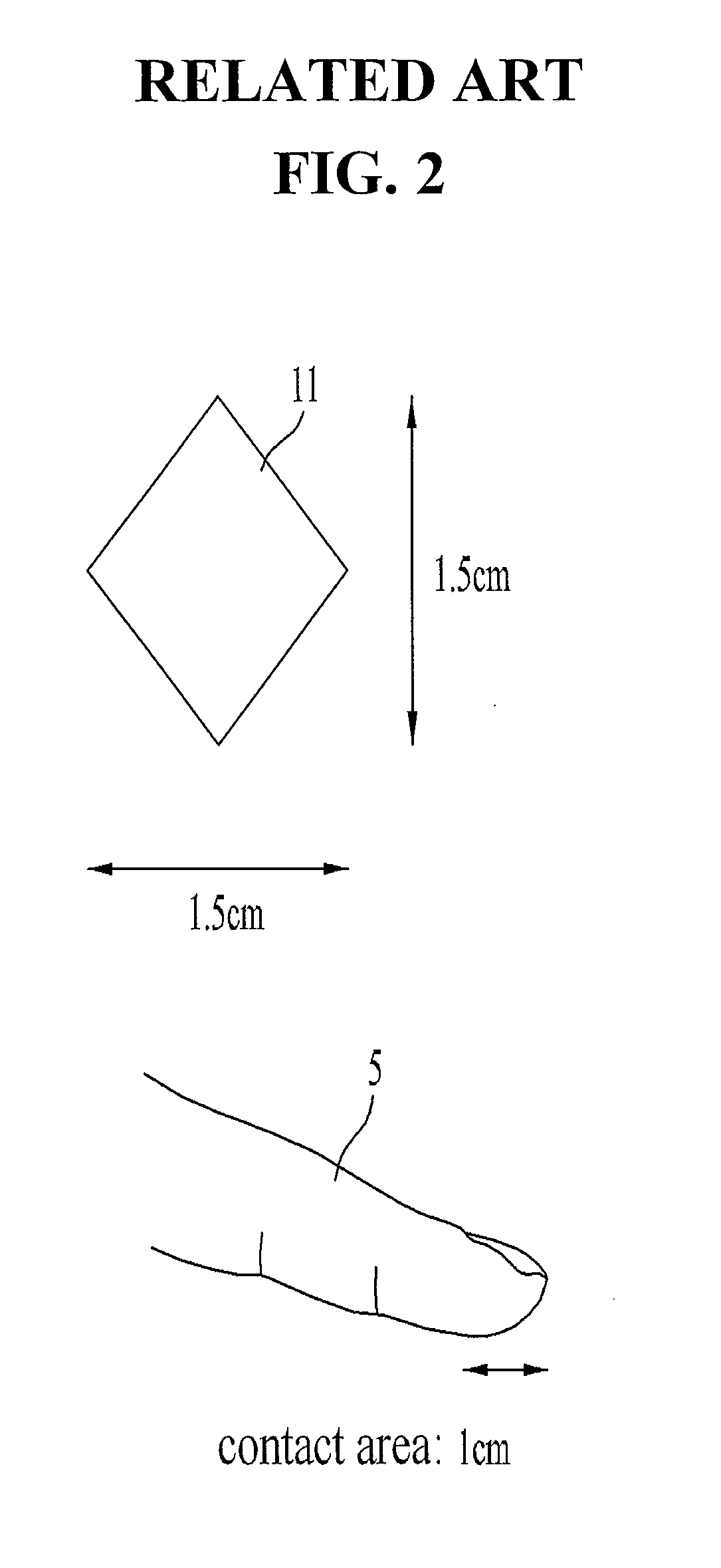
First of all, the pin number of the touch panel controller commercialized currently is limited and the electrode number corresponding to the pin number is limited accordingly. Because of that, the presentation of the touch panel is possible only in a compact-sized model. If the touch panel controller is applied to a more-than-medium-sized model, the size of the sensing electrode has to be larger and the single sensing area of the sensing electrodes is larger than the area of actual single touch area. As a result, minute motion which occurs in the single sensing area fails to be sensed and touch sensitivity has to be deteriorated.

Method used


Image

  • Touch panel including each touch controller for each divided region and liquid crystal display device using the same
  • Touch panel including each touch controller for each divided region and liquid crystal display device using the same
  • Touch panel including each touch controller for each divided region and liquid crystal display device using the same

Examples


first embodiment

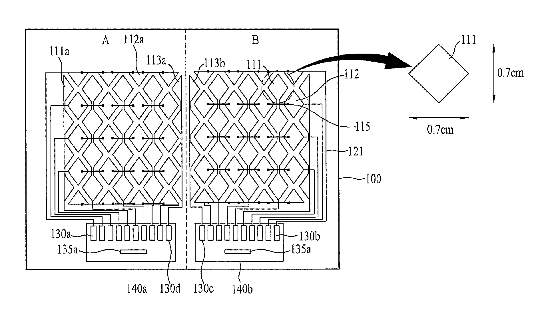
[0078]FIG. 4 is a plan view illustrating a touch panel according to the present invention and illustrating an example of a touch panel of related art having divisional driving applied thereto.

[0079]As shown in FIG. 4, the touch panel according to the first embodiment of the present invention includes first and second electrodes 111 and 112 crossingly aligned to each other on a substrate, at least two touch controller 135a and 135b formed in at least two divided regions (A and B) on the substrate 100 correspondingly to control applied signals and detected signals of the first and second electrodes 11 and 112 located in the divided regions correspondingly, a routing line 121 configured to connect the at least two touch controllers 135a and 135b with the first and second electrodes 111 and 112, and pad electrodes 130a and 130b connected with the routing line 121 and the at least two touch controllers 135a and 135b.

[0080]The touch controllers 135a and 135b are directly connected with t...

second embodiment

[0127]FIG. 10 is a plan view schematically illustrating a touch panel according to the present invention and FIG. 11 is a plan view specifically illustrating FIG. 10.

[0128]According to the second embodiment of the present invention, a configuration of electrodes may be presented to be more proper to the mutual capacitive type. The appearance of the electrodes may be changed into a rhombus pattern in a sensing area, different from the configuration of FIG. 8.

[0129]The drawings show four divided regions A, B, C and D. the rhombus pattern in each border area between the regions is divided into a triangle pattern and the triangle pattern is a second electrode border pattern 212a.

[0130]Separate FPCs 221, 222, 223 and 224 are provided in the regions, respectively.

[0131]In this case, the first electrodes 211 are formed of complete rhombus patterns connected with each other in all of the regions and border areas and outer lines of the first electrodes are corresponding to vertexs of the rh...


PUM


Abstract

A touch panel includes a substrate comprising divided regions; first electrodes, each of the first electrodes comprising first rhombus patterns spaced apart a predetermined distance from each other in a predetermined first direction and first connection patterns configured to connect the first rhombus patterns second electrodes, each of the second electrodes comprising second rhombus patterns spaced apart a predetermined distance from each other in the second direction and second connection patterns configured to connect the second rhombus patterns; third electrodes formed in border areas between the divided regions and outer areas of the divided regions; a touch controller formed in each of the divided regions correspondingly; and pad electrodes connected with the touch controller.

Description

CROSS REFERENCE TO RELATED APPLICATION[0001]This application claims the benefit of the Korean Patent Application No. 10-2009-0123109, filed on Dec. 11, 2009, which is hereby incorporated by reference as if fully set forth herein.BACKGROUND OF THE DISCLOSURE[0002]1. Field of the Disclosure[0003]The present invention relates to a touch panel, more particularly, to a touch panel having improved sensitivity embodied by applying divisional driving to a large-sized touch panel and changing a structure of a divided border area between divided areas while the divisional driving is implemented, and a liquid crystal display device including the touch panel.[0004]2. Discussion of the Related Art[0005]As the information age has started in earnest, a display field used to express an electrical information signal visually has been developed drastically. Together with that, a variety of flat display devices having excellent functions of slimming, reduced weights and low electricity consumption has...

Claims


Application Information

Patent Timeline
Patent Type & Authority Patents(United States)
IPC IPC(8): G06F3/041G06F3/044
CPCG06F3/044G06F3/0412G06F2203/04111G06F2203/04808G06F3/0446G02F1/13338G06F3/04164G06F3/041662G06F3/0448
Inventor KANG, HEE-KWANGLEE, DEUK-SUAN, SU-CHANGHAN, SUNG-SU
Owner LG DISPLAY CO LTD
Learn More