
Welding system having a power grid interface

a power grid and power grid technology, applied in the field of welding, heating and cutting systems, can solve the problems of affecting the power factor of the connected infrastructure, requiring substantial amounts of power, and system may represent substantial loads

Active Publication Date: 2015-07-28
ILLINOIS TOOL WORKS INC
View PDF48 Cites 12 Cited by
  • Summary
  • Abstract
  • Description
  • Claims
  • Application Information

AI Technical Summary

Benefits of technology

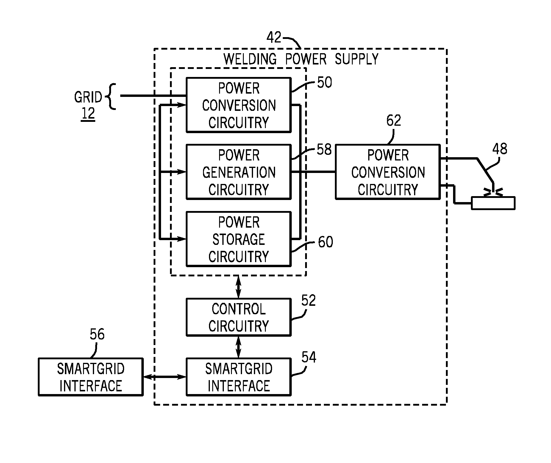
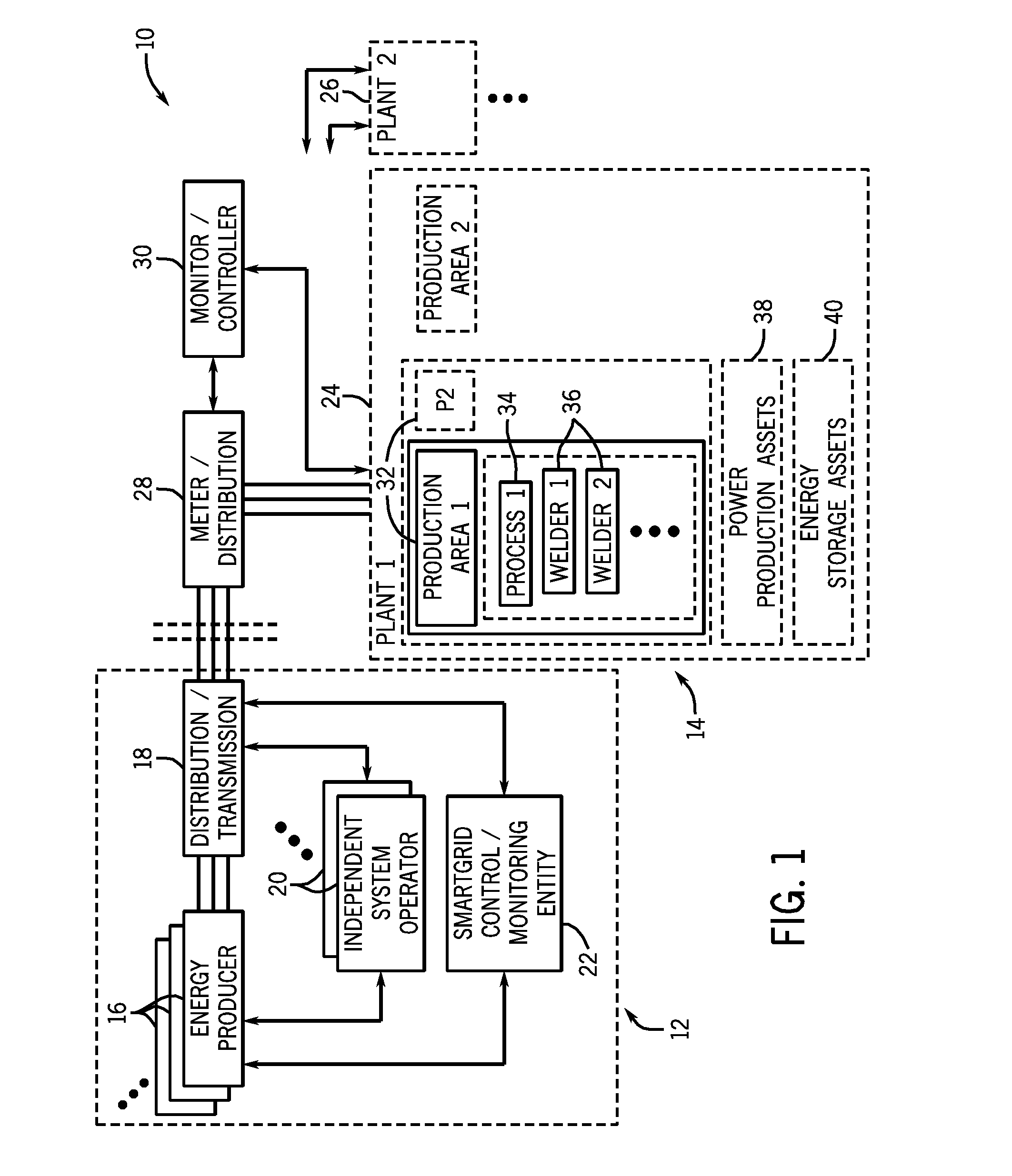
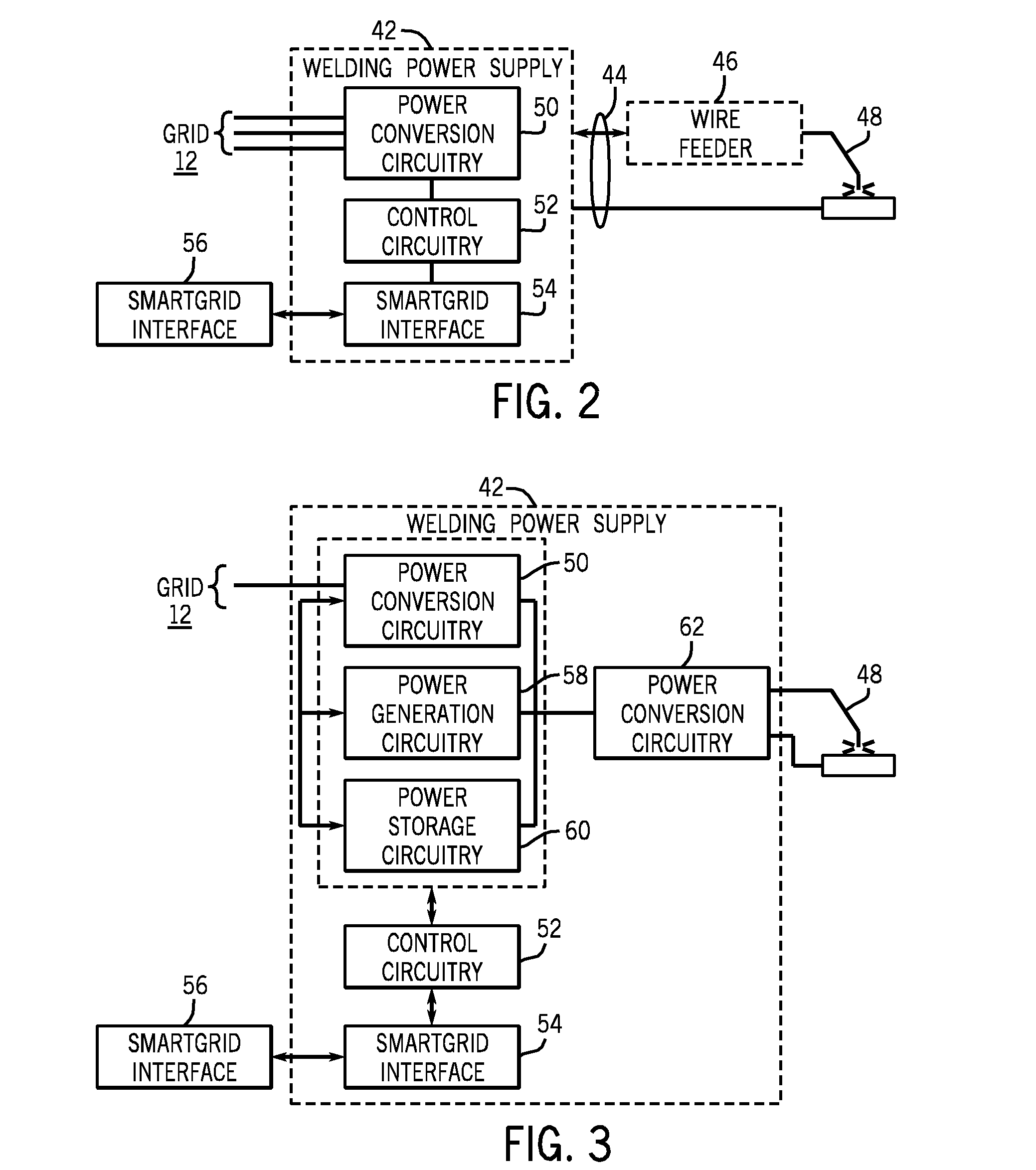
The present invention offers improved welding systems that can respond to different needs. These systems can be used for both arc welding and heating and cutting of work pieces. The invention can be scaled to various operations and can be incorporated into welding systems themselves. The monitoring and control functions can be performed at different levels, such as production area level, plant level, or enterprise level. The invention also allows for the intelligent coordination of both welding system loads and power production and storage. This allows for more coordinated production, storage, and usage of power in weld settings.

Problems solved by technology

Welding systems that rely on the creation of a welding arc have been refined to operate efficiently and effectively for joining metals in desired joints, but nevertheless requires substantial amounts of power.
When connected to the grid, these systems may represent substantial loads.
Moreover, the systems may alter the power factor of the connected infrastructure, requiring correction for efficient operation.
However, to date, little or no effort has been invested in intelligently coordinating operation of welding systems with the grid, or the coordination of alternative power sources from which the welding systems may draw the needed power with power from the grid.

Method used


Image

  • Welding system having a power grid interface
  • Welding system having a power grid interface
  • Welding system having a power grid interface

Examples


Embodiment Construction

[0014]As described more fully below, the systems, functionality and operation of welding equipment made available by the present invention provide for two-way data communication and where desired two-way power flow between welding systems and the power grid. In terms of the loads applied to the grid by welding and similar operations, this may allow for appropriate communication and timing of the onset and termination of welding operations. It may also allow for the planning of operations, scheduling of welding-based production operations, and the monitoring of power usage during such operations. Similarly, when welders or welding systems, or even production areas or entire production facilities include power generation capabilities, control of these assets can be based upon such factors as the availability of power from the grid, cost of power from the grid, peak and off-peak utilization, etc. In short, because of welding and similar operations may represent a substantial load that ...


PUM

PropertyMeasurementUnit
electrical poweraaaaaaaaaa
stored poweraaaaaaaaaa
store energyaaaaaaaaaa

Abstract

Welding system and method permit exchange of data with Smart Grid monitors and / or controllers. The welding systems include a welding power supply configured to convert power between the power grid and the welding power supply. A grid interface cooperates with control circuitry to transmit data to and / or from the grid monitors and / or controllers on the grid side. The control circuitry may control operation of the welding power supply based upon data from the grid. The system may include power generation devices (e.g., engine-drive generators) and energy storage devices (e.g., batteries). The control circuitry may control operation of such devices, the exchange of power between them, and the draw of power from the grid or the application of power to the grid based upon the data exchanged with the grid monitors and / or controllers.

Description

CROSS REFERENCE TO RELATED APPLICATIONS[0001]This application is a Non-Provisional Patent Application of U.S. Provisional Patent Application No. 61 / 297,344, entitled “Smart Grid Hybrid Welding System”, filed Jan. 22, 2010, which is herein incorporated by reference.BACKGROUND[0002]The present invention relates generally to welding, heating and cutting systems and to their operation in connection with Smart Grid connectivity and data exchange.[0003]Welding systems have become virtually ubiquitous throughout industry. Such systems are currently used in all industries, including manufacturing, physical plant construction, ship building, pipeline construction, maintenance and repair, etc. While variations exist in the system configurations and their modes of operation, many such systems are strictly electrical and rely upon the creation of a welding arc to melt and fuse base metals and / or adder metals, typically in the form of rods and wires. Currently available systems include, for exam...

Claims


Application Information

Patent Timeline
Patent Type & Authority Patents(United States)
IPC IPC(8): B23K26/00B23K9/10
CPCB23K9/1056B23K9/1075B23K9/1043
Inventor BUNKER, THOMAS A.ALBRECHT, BRUCE PATRICK
Owner ILLINOIS TOOL WORKS INC
Learn More