Method for cleaning semiconductor wafer
a technology for cleaning semiconductor wafers and semiconductors, applied in semiconductor/solid-state device manufacturing, basic electric elements, electric devices, etc., can solve the problems and achieve the effect of reducing metal impurity levels and particle levels on the surface of semiconductor wafers, and reducing effective and convenient effects
- Summary
- Abstract
- Description
- Claims
- Application Information
AI Technical Summary
Benefits of technology
Problems solved by technology
Method used
Image
Examples
example 1
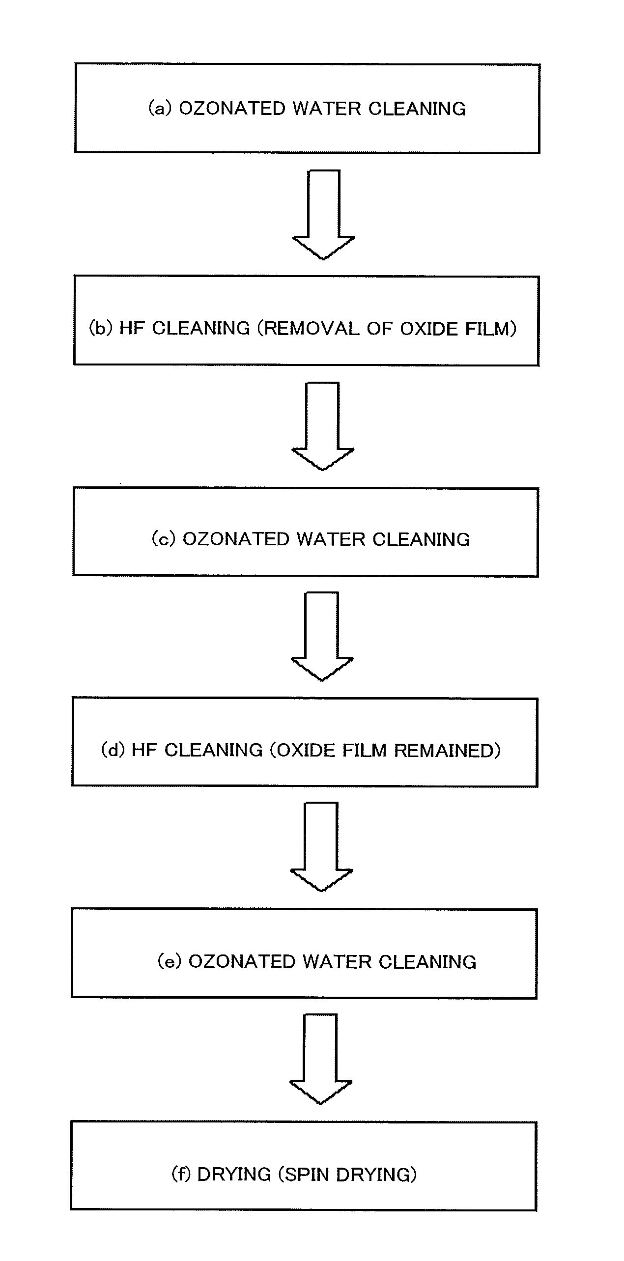
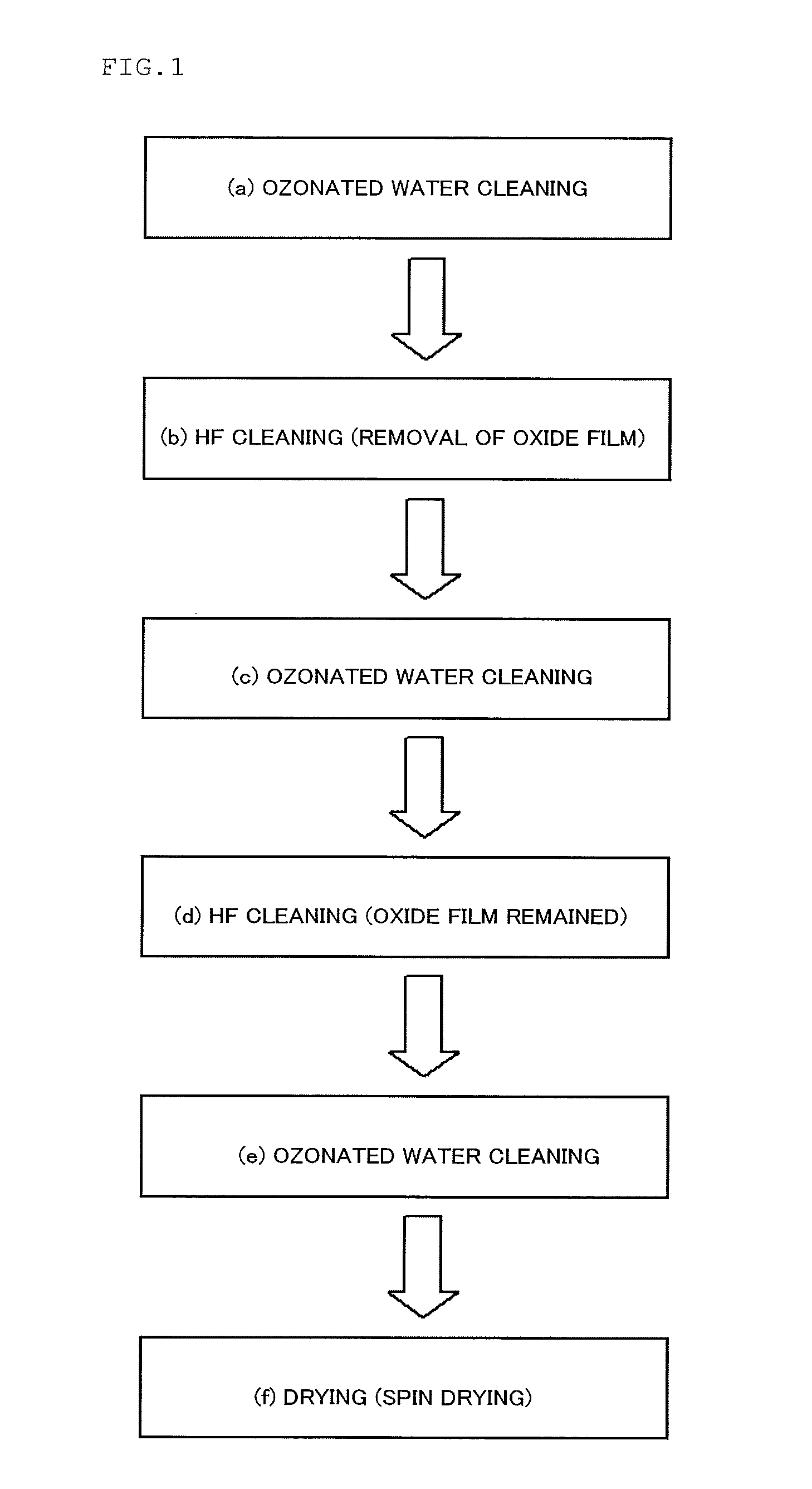
[0040]First, 15 wafers of silicon single crystal wafers having a diameter of 300 mm and both surfaces of which are mirror polished to have clean surfaces were prepared. Next, 3 wafers of the silicon single crystal wafers among the 15 wafers having clean surfaces were pulled out, and one of which was subjected to particle measurement by a wafer surface defect testing equipment (Particle counter, LS-6800 (≧41 nm) product of Hitachi High-Technologies Corporation) to examine the particle level before cleaning. As a result of the measurement, it could be found out that the wafer particle level before the cleaning was good level of 100 particles or less. Also, to examine concentrations of metal impurities attached to the surface before cleaning, 2 wafers thereof were subjected to vapor phase decomposition of a natural oxide film at the wafer surface by HF vapor, and then, the metal impurities on the wafer surface were recovered by HF liquid drops, and measurement of the concentrations of ...
example 2
[0046]Among the silicon single crystal wafers prepared in Example 1, 2 wafers thereof were subjected to cleaning as mentioned below, and measurement of the particle level and metal impurity level were carried out.
[0047]As shown in Table 1, cleaning of the silicon single crystal wafer was carried out in the same manner as in Example 1 except that the cleaning was carried out by repeating the ozonated water cleaning after the HF cleaning three times, where the oxide film formed on the surface of the silicon single crystal wafer was entirely removed at the first time HF cleaning, and in all the HF cleanings at the second time or later, the oxide film on the surface of the silicon single crystal wafer by the ozonated water cleaning was not entirely removed to remain a part of the thickness thereof on the surface of the silicon single crystal wafer.
[0048]Measurement of the particle level and the metal impurity level at the surface of the silicon single crystal wafer thus subjected to cle...
example 3
[0049]Among the silicon single crystal wafers prepared in Example 1, 2 wafers thereof were subjected to cleaning as mentioned below, and measurement of the particle level and metal impurity level were carried out.
[0050]As shown in Table 1, cleaning of the silicon single crystal wafer was carried out in the same manner as in Example 1 except that the cleaning was carried out by repeating the ozonated water cleaning after the HF cleaning four times, where the oxide film formed on the surface of the silicon single crystal wafer was entirely removed at the first time HF cleaning, and in all the HF cleanings at the second time or later, the oxide film on the surface of the silicon single crystal wafer by the ozonated water cleaning was not entirely removed to remain a part of the thickness thereof on the surface of the silicon single crystal wafer.
[0051]Measurement of the particle level and the metal impurity level at the surface of the silicon single crystal wafer thus subjected to clea...
PUM
| Property | Measurement | Unit |
|---|---|---|
| diameter | aaaaa | aaaaa |
| time | aaaaa | aaaaa |
| thickness | aaaaa | aaaaa |
Abstract
Description
Claims
Application Information
 - R&D
- Intellectual Property
- Life Sciences
- Materials
- Tech Scout
- Unparalleled Data Quality
- Higher Quality Content
- 60% Fewer Hallucinations
Browse by: Latest US Patents, China's latest patents, Technical Efficacy Thesaurus, Application Domain, Technology Topic, Popular Technical Reports.
© 2025 PatSnap. All rights reserved.Legal|Privacy policy|Modern Slavery Act Transparency Statement|Sitemap|About US| Contact US: help@patsnap.com


