Iron head
a technology of iron head and spherical head, which is applied in the field of iron head, can solve the problems of difficult to obtain a strong impact feeling, and achieve the effects of reducing the total weight of the iron head, enlarge the sweet area without increasing the total weight, and increasing the partial weigh
- Summary
- Abstract
- Description
- Claims
- Application Information
AI Technical Summary
Benefits of technology
Problems solved by technology
Method used
Image
Examples
second embodiment
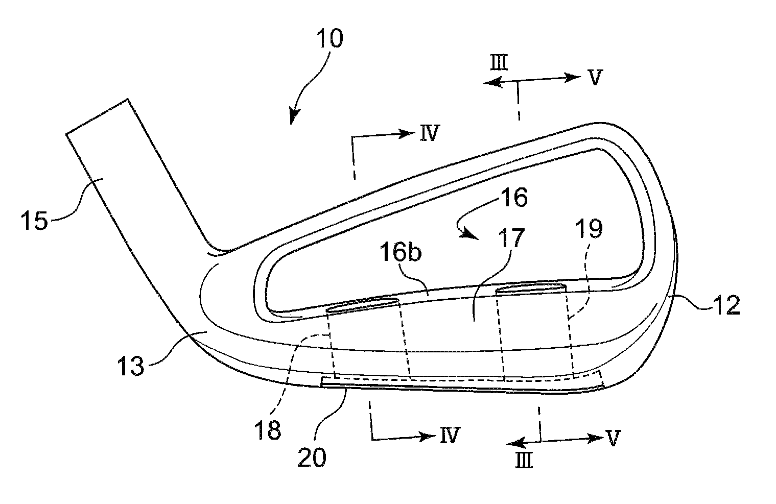
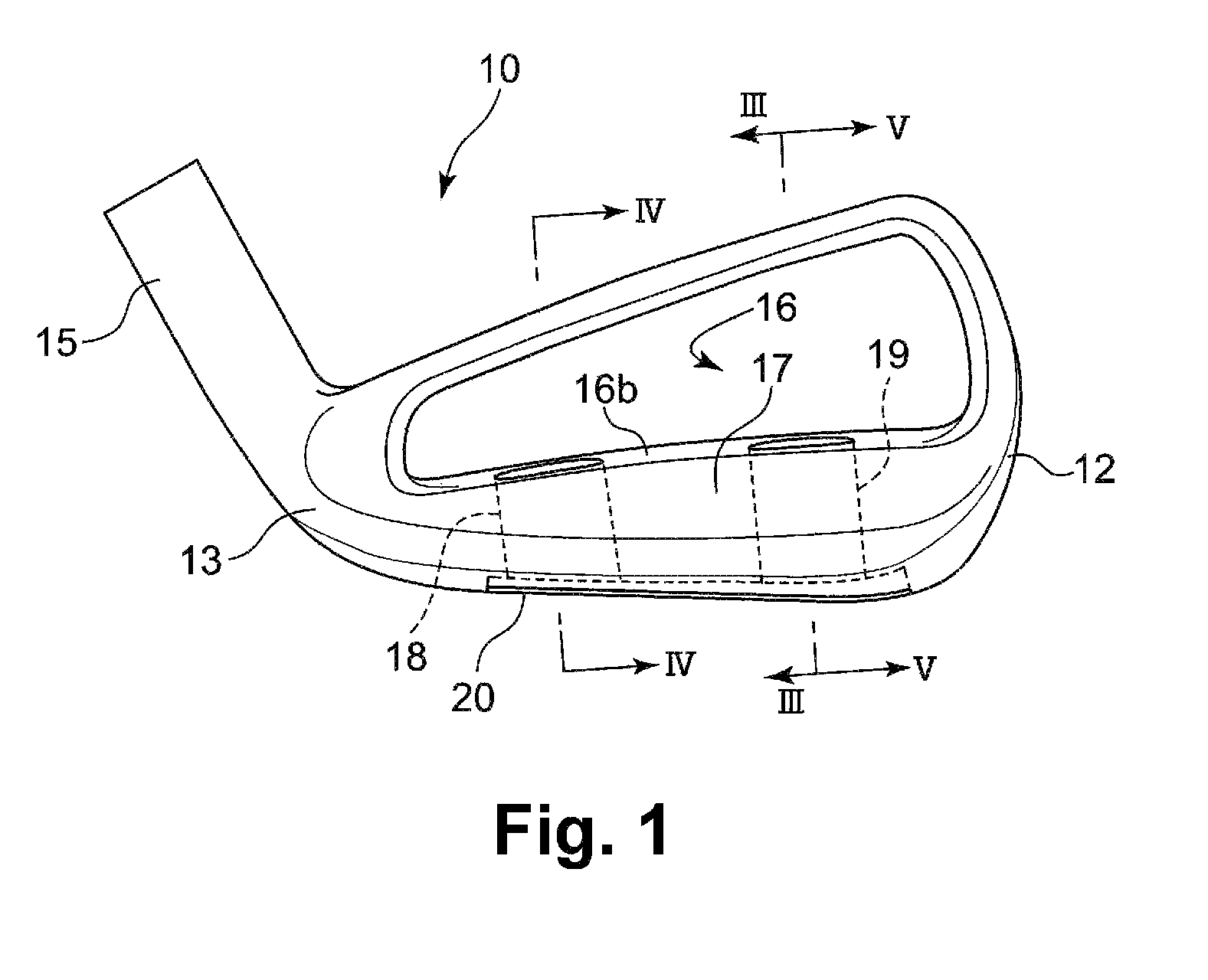
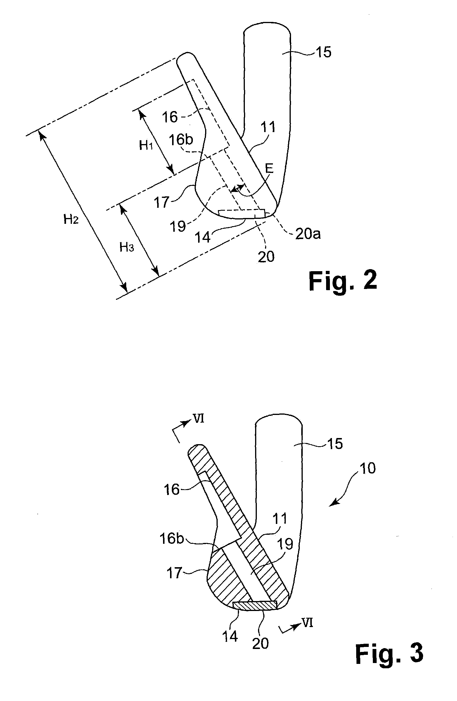
[0092]FIGS. 7 and 8 show an iron head 10A according to the second embodiment of the present invention. According to the first embodiment, the width W1 of the middle portion M in the toe to heel direction is substantially same from the upper end thereof to the lower end thereof. According to the second embodiment, instead of the hollow portions 18 and 19 in the first embodiment, the iron head 10A is provided with a hollow portion 18A disposed away from a hollow portion 19A by a distance gradually increasing from the upper surface of the protruding portion toward the sole surface.
[0093]It is desirable that the hollow portion 18A and the hollow portion 19A have a distance therebetween, at the top end thereof, being same as the width W1 mentioned above. Further, at the bottom end, it is desirable that the distance between the hollow portion 18A and the hollow portion 19A is equal to or less than 1.2 times, especially equal to or less than 1.1 times, of the distance between the hollow po...
third embodiment
[0094]In the first and second embodiments, the hollow portions 18, 19, 18A, and 19A have a width E, which is the thickness thereof in the vertical direction to the face surface. The width E is substantially same from the top end to the bottom end of the hollow portions 18, 19, 18A, and 19A. As shown in FIG. 9, in an iron head 10B according to the third embodiment, each of hollow portions 18B (not shown) and 19B has a thickness gradually increasing from the top end of the hollow portions toward the bottom end thereof. Further, the hollow portions 18B and 19B have a thickness, at the upper end thereof, being same as the width E in the first and second embodiments. It is desirable that the thickness of the bottom end of the hollow portions 18B and 19B is equal to or less than twice, especially equal to or less than 1.2 times, of that of the upper end thereof. Other configurations of the third embodiment are same as the first embodiment, and same reference numerals denote same component...
fourth embodiment
[0095]In the first and second embodiment, the hollow portions 18, 19, 18A, and 19A extend from the upper surface 16b of the protruding portion to the sole surface 14 in a parallel direction to the striking face 11. The distance between the hollow portions and the striking face 11, i.e., the thickness of the face plate, is substantially same from the top to the bottom thereof. As shown in FIG. 10, according to the fourth embodiment, an iron head 10C has a thickness of a face plate between hollow portions 18C (not shown) and 19C and the striking face 11 being gradually increasing from the top to the bottom thereof. Other configurations of the fourth embodiment are same as the first embodiment, and same reference numerals denote same components.
[0096]Further, in the first to fourth embodiments described above, the hollow portions 18, 19, 18A, 19A, 18B, 19B, 18C, and 19C are opened to the cavity portion 16, and lids (not shown) may be fixed to the upper ends of the hollow portions. A sa...
PUM
 Abstract
Description
Claims
Application Information
 - R&D
- Intellectual Property
- Life Sciences
- Materials
- Tech Scout
- Unparalleled Data Quality
- Higher Quality Content
- 60% Fewer Hallucinations
Browse by: Latest US Patents, China's latest patents, Technical Efficacy Thesaurus, Application Domain, Technology Topic, Popular Technical Reports.
© 2025 PatSnap. All rights reserved.Legal|Privacy policy|Modern Slavery Act Transparency Statement|Sitemap|About US| Contact US: help@patsnap.com


