
Optical space-time coding technique in microfluidic devices

a microfluidic device and optical space-time coding technology, applied in the field of microfluidics, can solve the problems of inconvenient operation, high design difficulty, and inability to achieve particle confinement in the out-of-plane direction, and achieve repeatable and controllable device characteristics, low design throughput, and easy operation. the effect of simple and convenient operation

Active Publication Date: 2015-07-07
RGT UNIV OF CALIFORNIA
View PDF10 Cites 26 Cited by
  • Summary
  • Abstract
  • Description
  • Claims
  • Application Information

AI Technical Summary

Benefits of technology

The patent describes how to measure the speed and position of particles or samples in a microfluidic channel, which can help in designing and testing lab-on-a-chip devices, like flow cytometers and point-of-care diagnostics. The technology works by using optical detection techniques, which are cheaper, portable, and easy-to-use. With this technology, researchers and clinicians can accurately and non-invasively measure particle distribution over the channel area, regardless of flow conditions and particle sizes. The technology also has applications in communication systems, where it can improve signal-to-noise ratios and detect weak signals using advanced digital signal processing techniques.

Problems solved by technology

Although this approach can be effective, the design can have a relatively low throughput which can become a limiting factor for certain applications.
For example, for many microfluidic devices, sheath flow can confine the particles in the in-plane direction, but can require special designs and more complex processes to achieve particle confinement in the out-of-plane direction.

Method used


Image

  • Optical space-time coding technique in microfluidic devices
  • Optical space-time coding technique in microfluidic devices
  • Optical space-time coding technique in microfluidic devices

Examples


Embodiment Construction

[0041]Microfluidic technologies can be used to enable highly integrated analytical devices to perform several different functions on the same substrate, chip, or platform. For example, microfluidic-based devices can facilitate the flow of suspended particles in a microfluidic channel directed in a stream to an interrogation area where optical or electrical characterizations is performed to reveal the intrinsic properties of the sample. Such optical or electrical characterization techniques can include optical scattering, fluorescence, Raman signals, and impedance detection. For example, based on the detected signals, particle separation methods may be applied to direct the particles to the designated downstream channels. Such methods may use various mechanisms including, e.g., hydrodynamic, dielectrophoretic, optical, acoustic or magnetic mechanisms. In some implementations in which the particles include living cells, cell sorting can be used to isolate subpopulations of cells from ...


PUM

PropertyMeasurementUnit
large angle scatteringaaaaaaaaaa
wavelengthsaaaaaaaaaa
heightaaaaaaaaaa

Abstract

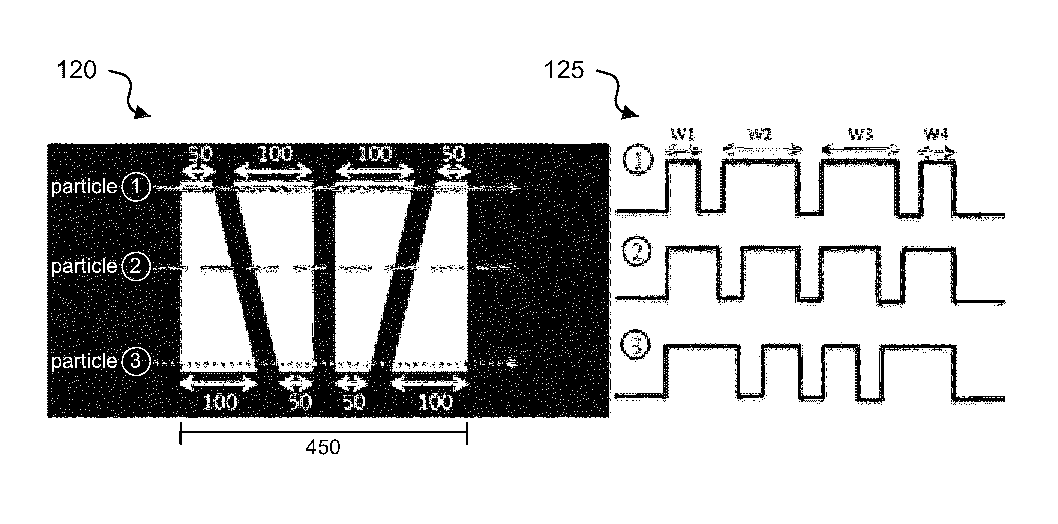
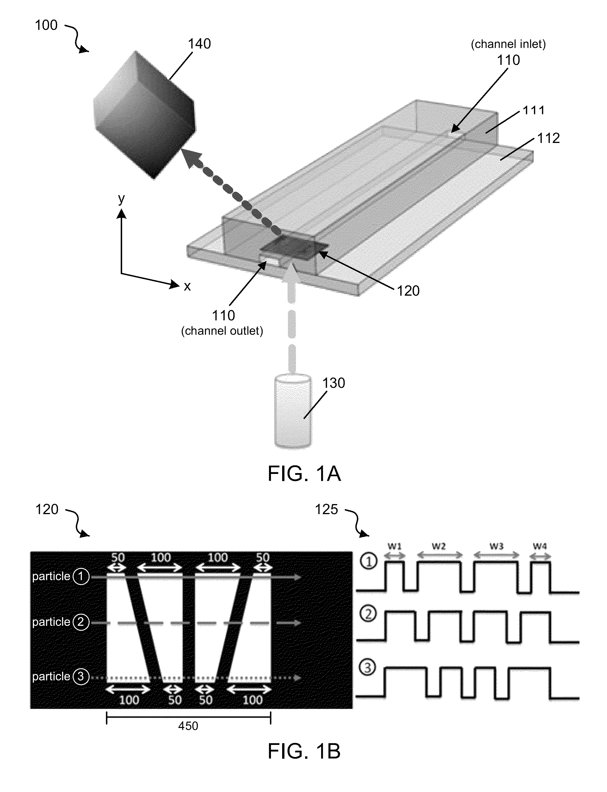
Techniques, devices and systems are disclosed for characterizing particles in a fluid sample by optical space-time coding. In one aspect, a microfluidic device for optical detection of particles includes a substrate, a microfluidic channel formed on the substrate and structured to carry a fluid sample containing particles, in which the microfluidic channel is structured to transmit a probe light, and a mask formed on one side of the microfluidic channel and structured to include a pattern of openings along the microfluidic channel, in which at least two of the openings have varying dimensions across the microfluidic channel, and in which the pattern of openings encodes a waveform on the probe light that transmits through the microfluidic channel to allow optical detection of a position of a particle in the microfluidic channel.

Description

PRIORITY CLAIM[0001]This patent document claims the priority of U.S. provisional application No. 61 / 507,068 entitled “OPTICAL SPACE-TIME CODING TECHNIQUE IN MICROFLUIDIC DEVICES” filed on Jul. 12, 2011, which is incorporated by reference as part of this document.STATEMENT REGARDING FEDERALLY SPONSORED RESEARCH OR DEVELOPMENT[0002]This invention was made with government support under grants R21RR024453 and R43RR031424-01 awarded by the National Institutes of Health (NIH). The government has certain rights in the invention.TECHNICAL FIELD[0003]This patent document relates to microfluidics.BACKGROUND[0004]Advances in micro-electromechanical technology have enabled the fabrication of microfluidic devices integrated with various functions that can be implemented in applications related to biology and medicine. A microfluidic device is an instrument that can control the behavior of very small amounts of fluid (e.g., such as nL, pL, and fL) through channels with dimensions in relatively sm...

Claims


Application Information

Patent Timeline
Patent Type & Authority Patents(United States)
IPC IPC(8): G01P3/36G01N15/14G01P5/00G01P5/20G01P5/26G01N15/10
CPCG01N15/1459G01P5/001G01P5/20G01P5/26G01N15/1484G01N2015/1006G01N2015/1486G01N2015/1493
Inventor LO, YU-HWAWU, TSUNG-FENGMEI, ZHE
Owner RGT UNIV OF CALIFORNIA
Learn More