
Electrostatic charge de-ionizing lightning rod for protection of wind turbine generator blades and wind turbine generator with blades provide with electrostatic charge de-ionizing lightning rod

a technology of electrostatic charge and lightning rod, which is applied in the direction of wind motors, wind motor components, wind energy generation, etc., can solve the problems of blade loss, fire risk, and inability to guarantee a complete protection of people or facilities,

Inactive Publication Date: 2015-07-07
CLAVERIA CANAL ANTONIO +3
View PDF11 Cites 0 Cited by
  • Summary
  • Abstract
  • Description
  • Claims
  • Application Information

AI Technical Summary

Benefits of technology

The de-ionizing lightning rod is designed to protect wind turbine generator blades from direct impact and reduce the risk of lightning strike. The rod is based on the principle of controlling the electric field at the tip of the blade to prevent ionization of the air. The continuous dissipation of electrostatic charge ensures that no lightning can be excited at the blade tip, which in turn protects the entire generator structure. The electric continuity is also guaranteed, from the blade tip to the ground circuit, minimizing the risk of severe lightning strike. The lightning rod is designed with a minimum section of at least 35 mm2 and over its entire route.

Problems solved by technology

These systems are unable to guarantee a complete protection to people or facilities as they are unable to control the polarity of lightning or to determine the intensity of the energy that will develop during the operation of the tip lightning rod.
In this case, the effort and work executed by this meteorological phenomenon (positive lightning) causes the destruction of material and, to a lesser extent, of electric equipment, since as lightning energy passes through in a fraction of a second it generates a thermodynamic work effort accompanied by instantaneous thermal effects, which transform in the segregation of part of the tip of the blade, causing a fire risk.
The blade then usually loses its aerodynamic properties; it starts vibrating and it eventually gets disengaged from its housing and is expelled, in some cases over a hundred meters away.
In the point of lightning impact on the blade, an instant direct fusion occurs with loss of material and risk of fire.
These effects generate, in the short term, a loss of mechanical resistance of the materials where the lightning current flows, resulting in an instant change of its physical characteristics, losing their flexibility and the mechanical resistance for which they were designed.
The electromagnetic effects due to the lightning impact and the current originate, as they pass through, couplings and inductions on the navigation electronics, which are in charge of the orientation of the self-generator based on the direction of the wind, losing temporary or permanent information, likewise directly affecting the electronic part that regulates braking, which could, after this moment, dangerously increase the generator's speed due to storm winds, reaching the overheating limits of the rotor's bearings as the blade's revolutions increase to their maximum limits.
This overheating can cause a fire of the oil in the aforementioned bearings, at which moment the generator enters a phase referred to as of “sacrifice” due to the velocity of these occurrences and the lack of necessary time for the disconnection of the generator from the grid, making it impossible to use water for the extinction as voltage is present on the set.
Once the fire has initiated in the generator compartment, it extends to the blades, which will detach in pieces, with the generator becoming destroyed, in a vertical or folded position, depending on the circumstances, finally generating losses in production and repair, with very high cost.
As conclusion for this description of the effects of lightning impact and the current protective techniques, it should be stated that the different protective systems placed on the blades have a pointed end and do not provide an effective protection.
Currently there are no protection systems that eliminate or limit the possibility of lightning impact on the blade, said systems being conceived for the capture of the lightning through excitation, channeling the lightning to the ground through tips.

Method used


Image

  • Electrostatic charge de-ionizing lightning rod for protection of wind turbine generator blades and wind turbine generator with blades provide with electrostatic charge de-ionizing lightning rod
  • Electrostatic charge de-ionizing lightning rod for protection of wind turbine generator blades and wind turbine generator with blades provide with electrostatic charge de-ionizing lightning rod

Examples


Embodiment Construction

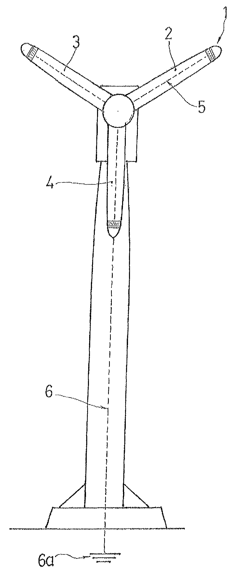
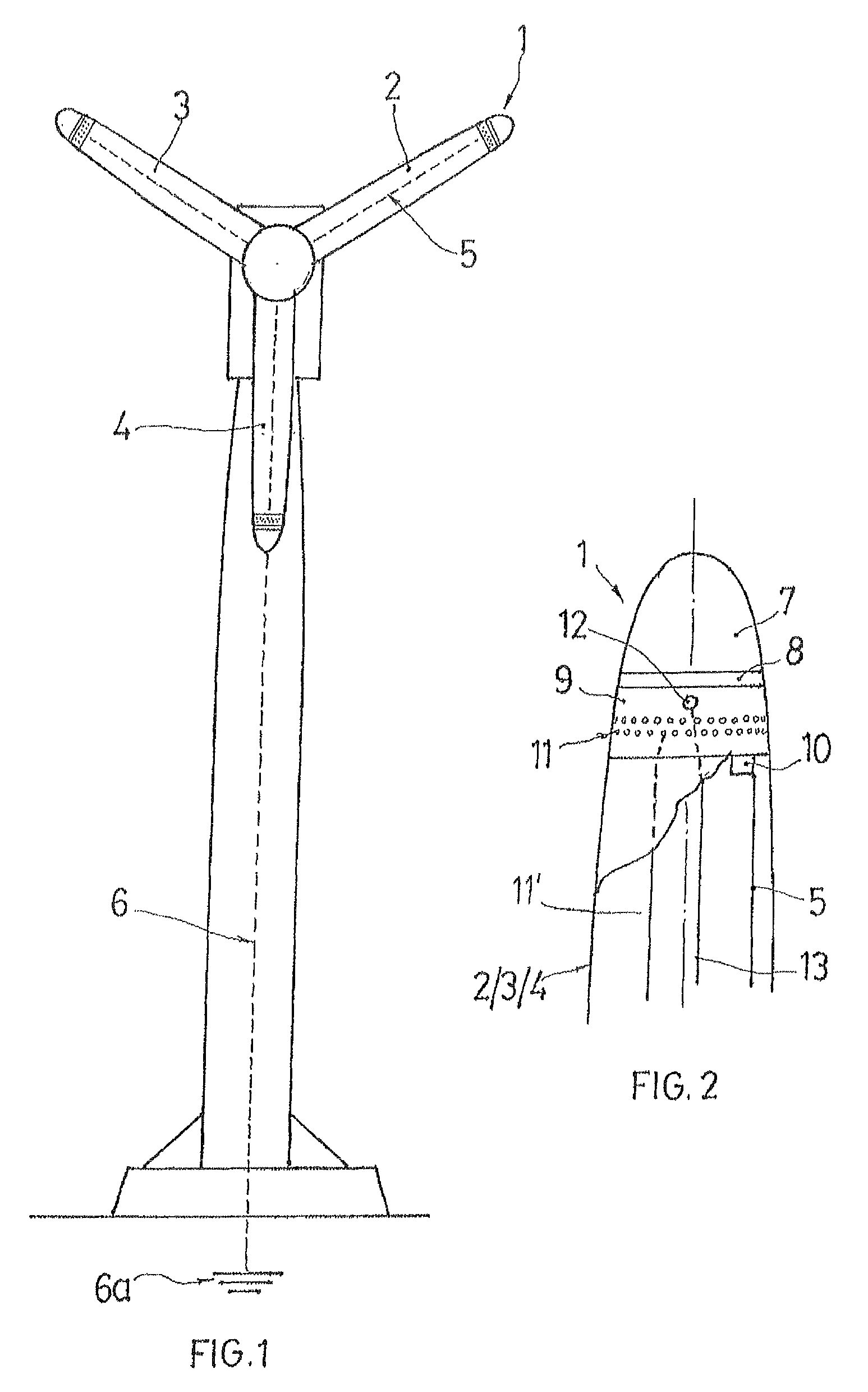
[0028]An electrostatic charge-ionizing lightning rod is identified as a whole with reference numeral 1. The de-ionizing lightning rod (1) is located on the tip of each of the blades (2, 3 and 4). With this location of the de-ionizing lightning rods (1), when the blades of the wind turbine are rotated, the lightning rods remain in the most salient area of a radius of rotation, or in other words of the radius of rotation of the blades (2, 3 and 4).

[0029]Each of the lightning rods (1) is connected through a corresponding conductor (5) to a conductor (6) or a ground circuit (6a) or to a grid of the ground circuit of a wind farm.

[0030]As shown in FIG. 2, the de-ionizing lighting rod (1) includes an exterior electrode (7), an isolating disc (8), and an interior electrode (9). A plurality of the isolating discs (8) can be located between the exterior electrode (7) and the interior electrode (9). The de-ionizing lightning rod (1) composed of the exterior electrode (7), the isolating disc / di...


PUM


Abstract

A lightning rod for blades of a wind turbine generator is attached to a corresponding blade, includes an exterior electrode of electric conductive material and mechanically resistant, preferably aluminum, separated by one or several isolating disks from an interior electrode, is connected through a mechanical or electric connector and the appropriate electric conductor to a conductor of the ground circuit, and is equipped with an LED battery and a probe for vibration control at the blade.

Description

CROSS-REFERENCE TO RELATED APPLICATION[0001]The invention described and claimed hereinbelow is also described in Spanish Patent Application ES 201130559 filed on Apr. 8, 2011. This Spanish Patent Application, whose subject matter is incorporated here by reference, provides the basis for a claim of priority of invention under 35 U.S.C. 119(a)-(d).BACKGROUND OF THE INVENTION[0002]The object of the present invention is an electrostatic charge de-ionizing lightning rod aimed at optimizing the protection of wind turbines against lightning action, specifically designed to reduce direct lightning impact over the blades of wind turbine generators.[0003]The object of the present invention is also to provide a wind turbine generator with blades having the electrostatic charge de-ionizing lightning rods of the invention.[0004]The present invention is related to on Spanish patent ES 200202884 in regard to protection against lightning action.[0005]There are several protection systems against lig...

Claims


Application Information

Patent Timeline
Patent Type & Authority Patents(United States)
IPC IPC(8): F03D1/02F03D11/00
CPCF03D11/0033Y02E10/722F03D80/30Y02E10/72
Inventor CLAVERIA CANAL, ANTONIORODRIGUEZ MONTES, ANGELHARO CERVANTES, DIEGOCOLL, MARGUERITE
Owner CLAVERIA CANAL ANTONIO
Learn More