Orthodontic supporting member
a support member and orthodontic technology, applied in dental surgery, dental tools, medical science, etc., can solve the problems of difficult to accurately adjust the position of the mini-implant, damage to the roots of the teeth, and difficulty in treating the teeth
- Summary
- Abstract
- Description
- Claims
- Application Information
AI Technical Summary
Benefits of technology
Problems solved by technology
Method used
Image
Examples
first exemplary embodiment
[0022
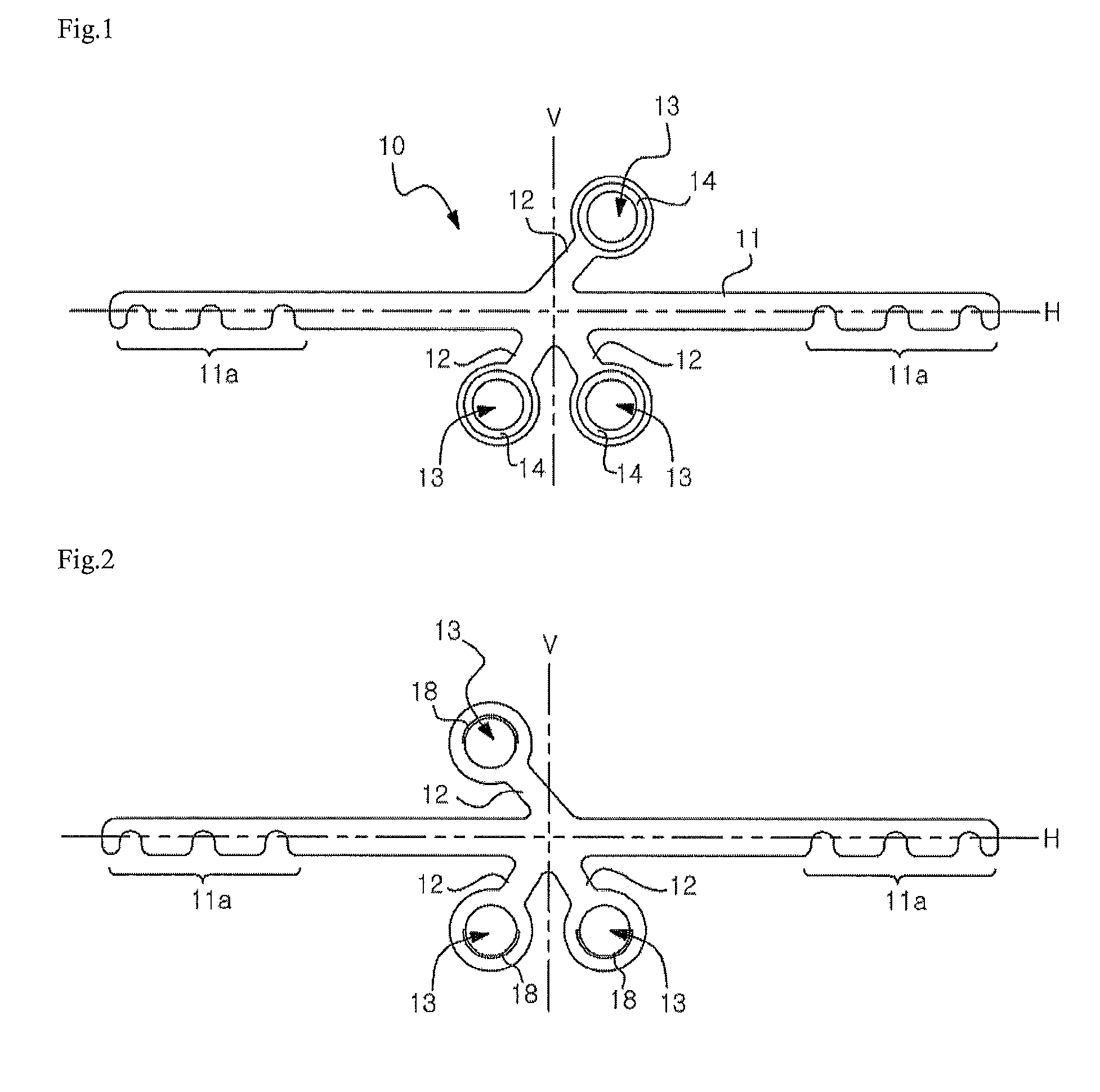
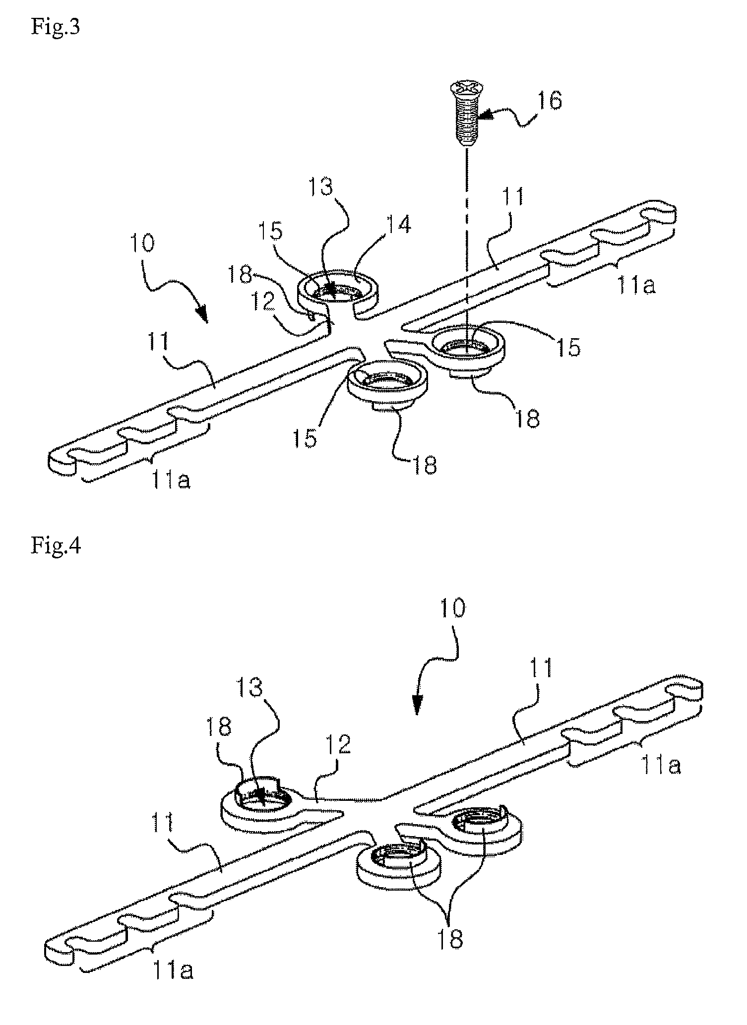
[0023]FIGS. 1 and 2 are respectively a top view and a bottom view of a support member 10 for correcting tooth irregularities, according to a first exemplary embodiment of the present invention. FIGS. 3 and 4 are respectively a top perspective view and a bottom perspective view of the support member 10 according to the first exemplary embodiment of the present invention.
[0024]The support member 10 according to the first exemplary embodiment includes a main body 11 that straightly extends and has hook portions 11a formed on both end portions thereof, and a plurality of leg portions 12 each of which extends from a central portion of the main body 11 and has a through-hole 13 formed in an end portion thereof.
[0025]Each of the leg portions 12 obliquely extends at a predetermined angle with respect to a second central line V perpendicular to a first central line H that extends in a longitudinal direction of the main body 11. Accordingly, as shown in FIGS. 1 and 2, the leg portions 12...
second exemplary embodiment
[0041
[0042]FIG. 6 is a top view of a support member 100 for correcting tooth irregularities, according to a second exemplary embodiment of the present invention. An overall structure of the support member 100, a process of providing the support member 100, and a function of the support member 100 of the present embodiment are the same as those of the support member 10 of FIGS. 1 through 4.
[0043]The support member 100 of the present exemplary embodiment is characterized in that a hook portion 110a is formed on an end portion of a main body 110, and a plurality of leg portions 120 radially extend on another end portion of the main body 110.
[0044]Each of the leg portions 120 obliquely extends at a predetermined angle with respect to the second central line V perpendicular to the first central line H that extends in a longitudinal direction of the main body 110.
[0045]Unlike the support member 10 according to the first exemplary embodiment, the support member 100 of the present exemplary...
third exemplary embodiment
[0048
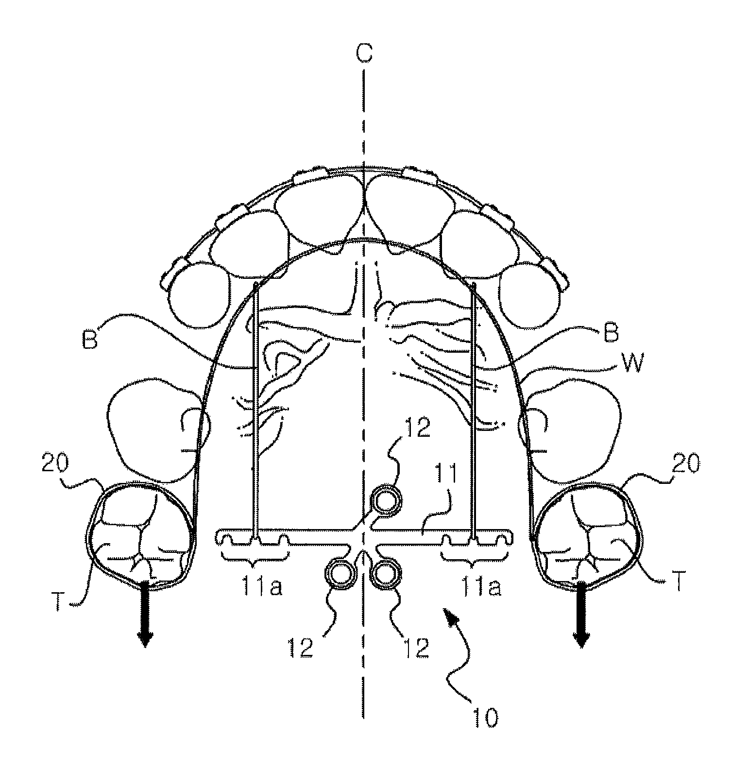
[0049]As shown in FIG. 5, the support member 10 or 100 may be used to correct tooth irregularities by applying an external force to the molars T toward the throat. However, in order to apply an external force to the molars T in an opposite direction, that is, toward lips, the wire W that connects the fixtures 20 mounted on the molars T has to be disposed on a portion around the throat instead of the lips.
[0050]Also, an elastic force of the elastic body B may be applied to the fixtures 20 only when there is a sufficient distance between the wire W that connects the fixtures 20 and the hook portion 11a or 110a of the support member 10 or 100.
[0051]To this end, the support member 10 or 100 may be fixed to a portion of the palatine bone close to the lips instead of the throat. However, since a width of an area close to the lips is less than a width of an area close to the throat due to a structure of the oral cavity, it is not preferable to use the support member 10 according to th...
PUM
 Abstract
Description
Claims
Application Information
 - R&D
- Intellectual Property
- Life Sciences
- Materials
- Tech Scout
- Unparalleled Data Quality
- Higher Quality Content
- 60% Fewer Hallucinations
Browse by: Latest US Patents, China's latest patents, Technical Efficacy Thesaurus, Application Domain, Technology Topic, Popular Technical Reports.
© 2025 PatSnap. All rights reserved.Legal|Privacy policy|Modern Slavery Act Transparency Statement|Sitemap|About US| Contact US: help@patsnap.com


