Eureka AIR delivers breakthrough ideas for toughest innovation challenges, trusted by R&D personnel around the world.

Wind tunnel rectification device

A technology of rectification device and wind tunnel, which is applied in the field of wind tunnel test, can solve the problems of rectifier stable section sloshing and small impact of airflow, etc., and achieve the effect of stable overall structure, convenient taking out and putting back, and convenient reorganization

Active Publication Date: 2014-09-03
NAT UNIV OF DEFENSE TECH
View PDF5 Cites 11 Cited by
  • Summary
  • Abstract
  • Description
  • Claims
  • Application Information

AI Technical Summary

Problems solved by technology

[0004] In general air-breathing wind tunnels, rectifiers are generally placed directly in the stable section of the wind tunnel due to the small impact of the airflow. When rectifiers are used in blowing wind tunnels, the fixation of rectifiers must be considered

Method used


Image

  • Wind tunnel rectification device
  • Wind tunnel rectification device
  • Wind tunnel rectification device

Examples


Embodiment Construction

[0029] The present invention will be described in detail below in conjunction with the accompanying drawings.

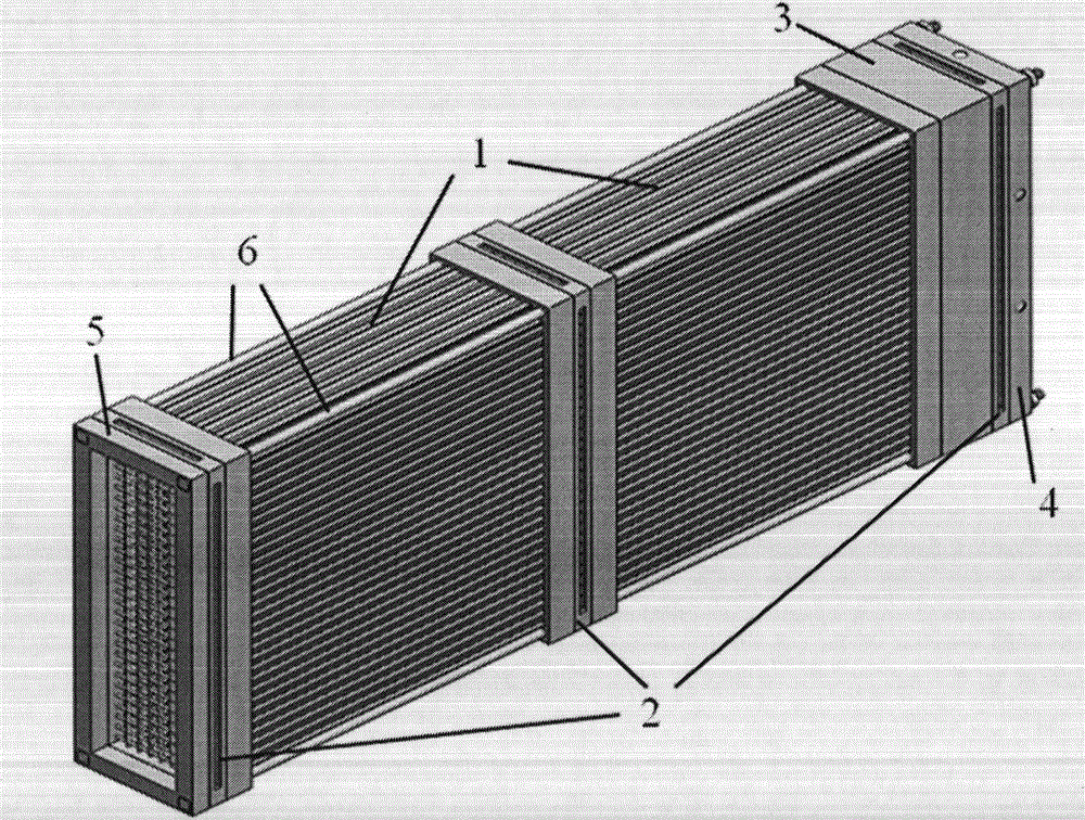
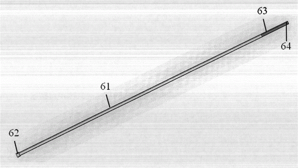
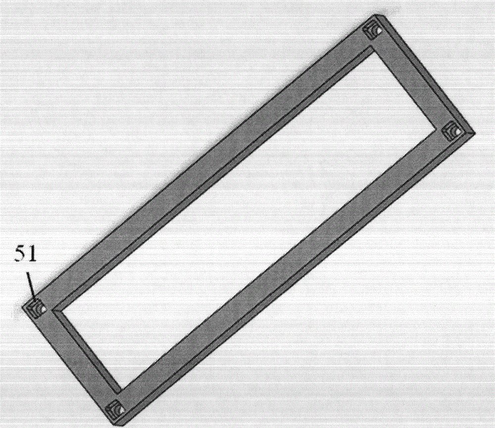
[0030] The present invention includes a honeycomb 1, a damping net 2, a connecting section 3, a front end 4, a rear end 5 and a strut 6. The honeycomb 1, the damping net 2, the connecting section 3, the front end 4 and the rear end 5 are connected and locked by the strut 6, and the fixed screw 41 of the front end 4 is integrally fixed in the stable section of the wind tunnel. Each part of the rectifier is an independent functional module, in which the front end 4 and the rear end 5 are respectively located on the outermost side, the honeycomb 1, the damping net 2 and the connecting section 3 are located between the front end and the rear end, and can be flexibly changed relative to each other. position, the strut connects and clamps the remaining parts in series to form a whole.

[0031] The honeycomb is an independent functional module, including a honeycomb 11 and...


PUM


Abstract

The invention provides a wind tunnel rectification device which comprises a honeycomb device, a damping net, a front end head, a back end head and supporting rods. The honeycomb device comprises a honeycomb and a honeycomb and honeycomb clamp covers, wherein the honeycomb is clamped by the honeycomb clamp covers. The internal flow passage edge of the honeycomb device is flush with the internal flow passage edge of a stable section. The damping net comprises a steel wire net and damping net clamp covers, wherein the steel wire net is fixedly connected with the damping net clamp covers. The internal flow passage edge of the damping net is flush with the internal flow passage edge of the stable section. The internal flow passage of the back end head is rectangle in shape, and the inner edge is flush with the internal flow passage edge of the stable section. The internal flow passage of the front end head is rectangle in shape, and the edge is flush with the internal flow passage edge of the stable section. The front end head is fixedly arranged in the stable section of a wind tunnel. The honeycomb device, the damping net and a connecting section are arranged between the front end head and the back end head. The relative position of the honeycomb device, the damping net and the connecting section can be changed. The honeycomb device, the damping net, the front end head and the back end head are connected and locked tightly through the supporting rods. The wind tunnel rectification device is stably and fixedly arranged in the stable section of the wind tunnel, thereby not introducing new turbulent flow; the positions of the honeycomb device and the damping net can be changed flexibly; and the whole structure is simple, and convenient installation is achieved.

Description

technical field [0001] The invention relates to the wind tunnel test technology in the field of aerospace, in particular to the design of a wind tunnel rectifying device. Background technique [0002] In boundary layer research, shear layer research, and jet-jet mixing research, the quality of the flow field in the wind tunnel is high, especially in supersonic wind tunnels, the quality of the flow field behind the nozzle is heavily dependent on the flow in front of the nozzle In order to obtain a uniform flow field, the flow field in front of the nozzle must be as uniform, stable and low in turbulence as possible. In order to obtain a uniform flow field, common methods include extending the stable section, installing rectifiers, and using boundary layer suction. The rectifier is widely used because of its simple structure and good rectification effect. [0003] The rectifier is generally composed of a damping net and a honeycomb. Due to the complexity of the flow field of ...

Claims


Application Information

Patent Timeline
Patent Type & Authority Applications(China)
IPC IPC(8): G01M9/04
Inventor 吴里银赵延辉王振国
Owner NAT UNIV OF DEFENSE TECH
Why Eureka
Eureka Blog
Learn More