Large multiplier for programmable logic device

a programmable logic and multiplier technology, applied in the field of programmable logic devices, can solve the problems of increasing complexity of applications for which plds are used, slow and less efficient, and consuming general-purpose resources that might be put to other uses, so as to reduce or eliminate the reliance on general-purpose programmable resources and facilitate the performance of multiplication

Inactive Publication Date: 2015-06-23
ALTERA CORP
View PDF389 Cites 1 Cited by
  • Summary
  • Abstract
  • Description
  • Claims
  • Application Information

AI Technical Summary

Benefits of technology

[0007]The present invention relates to specialized processing blocks for PLDs that are provided with logic within the blocks to facilitate the performance of multiplications larger than that which can be performed within any single specialized processing block, reducing or eliminating reliance on general-purpose programmable resources of the PLD.
[0008]In accordance with the invention, control is provided over whether one or more multiplicand inputs are forced to be unsigned or are allowed to be signed. This enables the performance of more of the calculations involved in signed or complex multiplications. The ability to shift results—either within or outside the block—before further processing, further increases the number of types of calculations that can be performed.

Problems solved by technology

As applications for which PLDs are used increase in complexity, it has become more common to design PLDs to include specialized processing blocks in addition to blocks of generic programmable logic resources.
While the multipliers from several DSP blocks can be used together to implement double-precision multiplication, or larger complex multiplication, the logic needed to interconnect the multipliers has heretofore been programmed by the user in the general-purpose programmable logic outside the DSP block, making it slow and less efficient, and consuming general-purpose resources that might be put to other uses.

Method used


Image

  • Large multiplier for programmable logic device
  • Large multiplier for programmable logic device
  • Large multiplier for programmable logic device

Examples


embodiment 50

[0040]In embodiment 50, each half-block 51, 52 (and half-block 53, but not all components are shown because only one multiplier 530 is used from that half-block 53) preferably has four 18-bit-by-bit multipliers 510-513, 520-523, preferably arranged in pairs 510-511, 512-513, 520-521 and 522-523, with the output of the members of each pair preferably being added together by respective 54-bit adders 541-544 after the output of one member of pair has been shifted left 18 bits by respective shifter 55. One or more of shifters 55 may be programmably bypassable (not shown) as in the embodiment of FIGS. 3 and 4, above, but in this embodiment, for performing a 54-bit-by-54-bit multiplication, shifters 55 preferably are not bypassed (even if they are bypassable).

[0041]In the specialized processing block described in above-incorporated application Ser. No. 11 / 447,472, the output of adder 541, and the output of adder 542 after being shifted left 18 bits by shifter 545, would be added by 3:2 co...

embodiment 70 (fig.7)

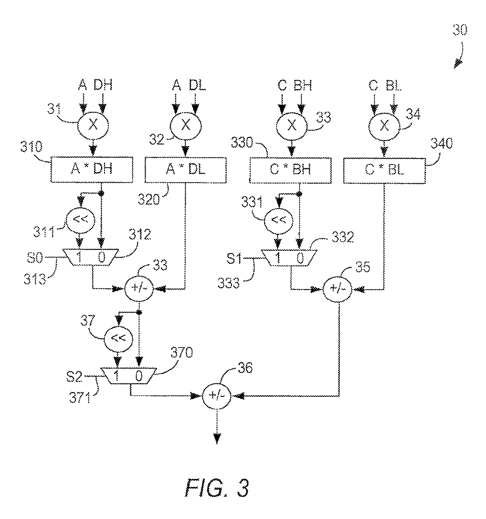
[0050]Embodiment 70 (FIG. 7) can compute the real part of a 36-bit-by-18-bit complex multiplication, as well as the imaginary part if signed multiplication is required. For example, the real part can be rewritten as:

Real: [((AH×B)AL×B)]+[((CH×(−D))CL×(−D))]

In embodiment 70, as in embodiment 30, the two first level shifters 311, 331 are used, and the second level shifter 37 is bypassed. In addition, at least the second multiplicands of multipliers 33 and 34 are not forced to unsigned mode, allowing the negated value of D to be input to those multipliers. This requires that the negation of D take place in other circuitry or in programmable logic of the PLD. The inputs to multipliers 33, 34 can be made unforced by connecting a respective one of multiplexers 71, 72 to the respective sign control inputs 73 of multipliers 33, 34, allowing each sign control input 73 to be connected either to ground (forced to unsigned) or to the sign control signal associated with the respective multiplica...


PUM


Abstract

A plurality of specialized processing blocks in a programmable logic device, including multipliers and circuitry for adding results of those multipliers, can be configured as a larger multiplier by adding to the specialized processing blocks selectable circuitry for shifting multiplier results before adding. In one embodiment, this allows all but the final addition to take place in specialized processing blocks, with the final addition occurring in programmable logic. In another embodiment, additional compression and adding circuitry allows even the final addition to occur in the specialized processing blocks. Circuitry that controls when an input is signed or unsigned facilitates complex arithmetic.

Description

CROSS REFERENCE TO RELATED APPLICATION[0001]This is a division of commonly-assigned U.S. patent application Ser. No. 11 / 682,787, filed Mar. 6, 2007, now U.S. Pat. No. 8,386,553, which is a continuation-in-part of commonly-assigned U.S. patent application Ser. No. 11 / 566,982, filed Dec. 5, 2006 and copending therewith, each of which is hereby incorporated by reference herein in its respective entirety.BACKGROUND OF THE INVENTION[0002]This invention relates to programmable logic devices (PLDs), and, more particularly, to the use of specialized processing blocks which may be included in such devices to perform large multiplications.[0003]As applications for which PLDs are used increase in complexity, it has become more common to design PLDs to include specialized processing blocks in addition to blocks of generic programmable logic resources. Such specialized processing blocks may include a concentration of circuitry on a PLD that has been partly or fully hardwired to perform one or mo...

Claims


Application Information

Patent Timeline
Patent Type & Authority Patents(United States)
IPC IPC(8): G06F7/53G06F17/10
CPCG06F17/10G06F7/5324
Inventor LANGHAMMER, MARTINTHARMALINGAM, KUMARA
Owner ALTERA CORP
Why Eureka
Try Eureka