Exhaust post-treatment device and method for a vehicle, with a reductant vaporising surface being warmed by a Peltier element

a technology of exhaust gas and peltier element, which is applied in the direction of exhaust treatment electric control, machines/engines, mechanical equipment, etc., can solve problems such as pressure drop

Inactive Publication Date: 2015-06-23
SCANIA CV AB
View PDF13 Cites 10 Cited by
  • Summary
  • Abstract
  • Description
  • Claims
  • Application Information

AI Technical Summary

Benefits of technology

[0010]The object of the present invention is to propose an exhaust post-treatment device for a vehicle and a method for post-treatment of exhaust gases from vehicles, which device can operate even if the temperature of the exhaust gases is low.
[0011]The above object is achieved according to the invention by an exhaust post-treatment device according to the invention and a method for post-treatment of exhaust gases from vehicles according to the invention. An exhaust post-treatment device for a vehicle, which is adapted to reducing nitrogen oxides present in the vehicle's exhaust gases by supplying liquid reducing agent to the exhaust gases is placed in an exhaust pipe. The device comprises a Peltier element and is adapted to locally warming a surface within the exhaust pipe by means of a Peltier element by using thermal energy from the exhaust gases to vaporise liquid reducing agent which reaches the surface. A method for post-treatment of exhaust gases from vehicles by supplying liquid reducing agent to the exhaust gases in an exhaust pipe in order to reduce nitrogen oxides present in the gases, presents the characteristic of locally warming a surface within the exhaust pipe using an exhaust post-treatment device comprising a Peltier element. This uses thermal energy from the exhaust gases to vaporise liquid reducing agent which reaches the surface. The device and method achieve the advantage that formation of deposits of reducing agent within the exhaust pipe is avoided even if the temperature of the exhaust gases is low. A further advantage is that the Peltier element has no movable parts and a consequent robust configuration.
[0012]According to an embodiment of the invention, one side of the Peltier element is adapted to diverting thermal energy from the exhaust gases to the Peltier element by the energy being absorbed on one side of the Peltier element. The other side of the Peltier element is adapted to locally warming a surface within the exhaust pipe by thermal energy being delivered from the Peltier element to the surface within the exhaust pipe, thereby achieving the advantage that the exhaust post-treatment device needs only moderate amounts of energy for its operation.
[0013]According to a further embodiment of the invention, the Peltier element comprises at least two electrodes made of different semiconductive metals such that every other or second electrode is of N type and the alternate electrodes are of P type. The electrodes are arranged to extend from one side of the Peltier element to the other side of the Peltier element and are connected in series via conductors to a direct-current source. Closing the electric circuit causes electrons in the N type electrode to move in the opposite direction to the current, and holes in the P type electrode to move in the direction of the current. Both of them divert heat from one side of the Peltier element to the other side of the Peltier element, thereby achieving the advantage that the configuration of the exhaust post-treatment device is adaptable, e.g. depending on the desired effect of the Peltier element.
[0014]According to further embodiments of the invention, the thermal energy absorption side of the Peltier element may be situated at least partly within the exhaust pipe or adjacent to the outside of the exhaust pipe. The thermal energy absorption side of the Peltier element may be situated downstream or upstream of the supply device for supply of liquid reducing agent to the exhaust gases in the exhaust pipe, as seen in their direction of flow. The thermal energy delivery side of the Peltier element may be situated adjacent to the outside of the exhaust pipe or at least partly within the exhaust pipe. The surface which is locally warmed within the exhaust pipe may be a surface of the thermal energy delivery side of the Peltier element which is situated within the exhaust pipe, or a surface on the inside of the exhaust pipe. A catalyst may be provided in the exhaust pipe downstream of the supply device for the liquid reducing agent, as seen in the direction of flow of the exhaust gases. A control unit may be provided to control the Peltier element and the supply of liquid reducing agent, thereby achieving the advantage that the configuration of the exhaust post-treatment device is adaptable, e.g. depending on whether high efficiency or simple configuration and easy assembly is prioritised.
[0018]thereby achieving the advantage that the exhaust post-treatment device needs only moderate amounts of energy for its operation.

Problems solved by technology

Using liquid urea solution may entail problems at low exhaust temperatures in that the reducing agent injected does not become vaporised quickly enough, with consequent formation in the exhaust system of deposits which may lead to pressure drop.
This presents a problem which is solved by maintaining such a high exhaust temperature that the reducing agent injected becomes vaporised in the exhaust pipe.

Method used


Image

  • Exhaust post-treatment device and method for a vehicle, with a reductant vaporising surface being warmed by a Peltier element
  • Exhaust post-treatment device and method for a vehicle, with a reductant vaporising surface being warmed by a Peltier element
  • Exhaust post-treatment device and method for a vehicle, with a reductant vaporising surface being warmed by a Peltier element

Examples


first embodiment

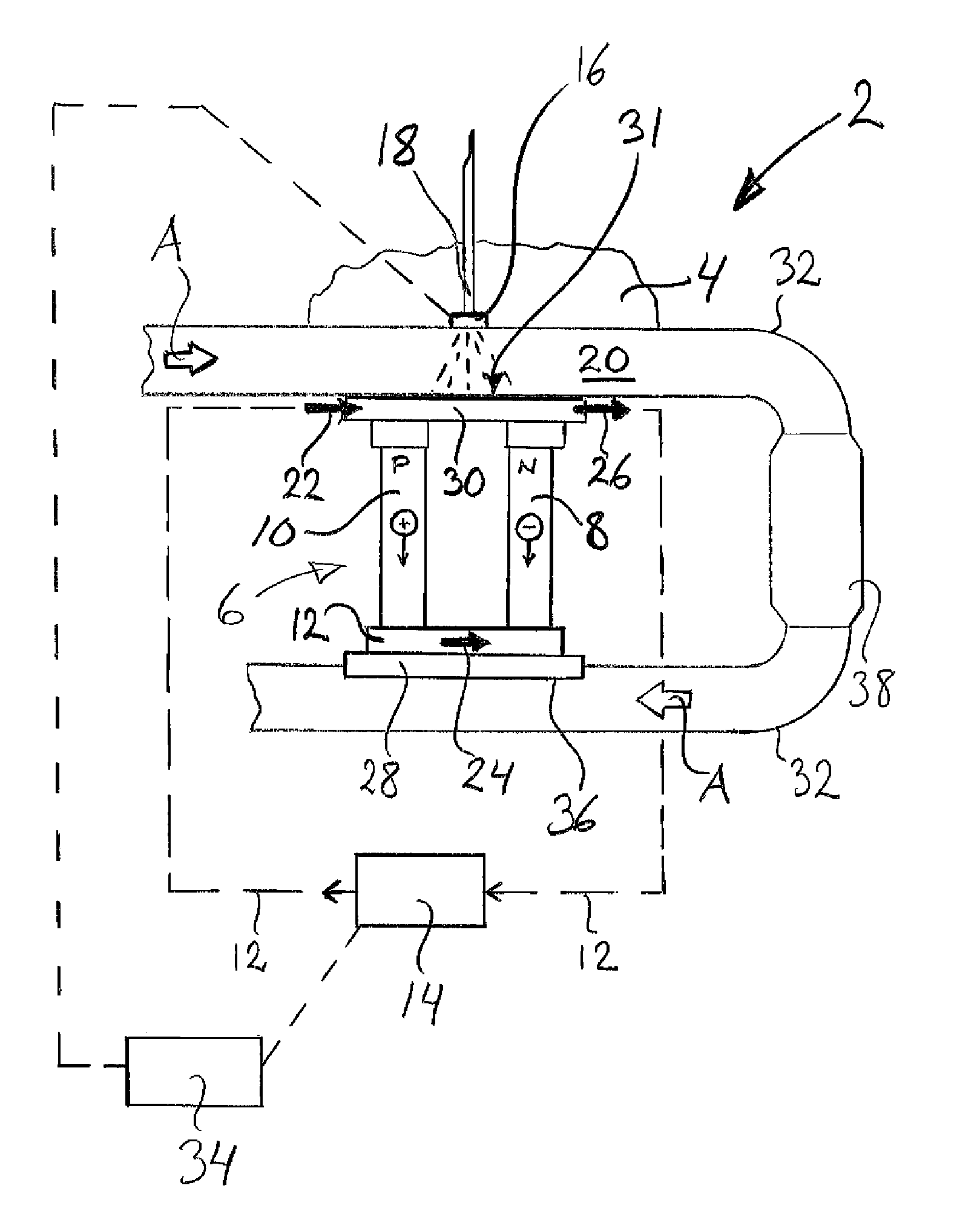
[0026]FIG. 1 depicts schematically an exhaust post-treatment device 2 for a vehicle 4 according to the invention, which device 2 comprises a Peltier element 6 also called a thermoelectric cooling element. The Peltier element 6 itself comprises at least one “thermocouple” composed of two electrodes 8, 10 made of different semiconductive metals. Every second electrode 8 is of N type and the alternate electrodes 10 are of P type. The electrodes 8, 10 are arranged to extend from one side 28 of the Peltier element 6 to the other side 30 of the Peltier element. The electrodes are connected in series via conductors 12, preferably made of copper, to a direct-current source 14, such that closing the electric circuit causes electrons in the N type electrode to move in an opposite direction to the current, and holes in the P type electrode to move in the direction of the current, as illustrated in the diagram, both of them diverting heat from one side 28 of the Peltier element 6 to the other s...

second embodiment

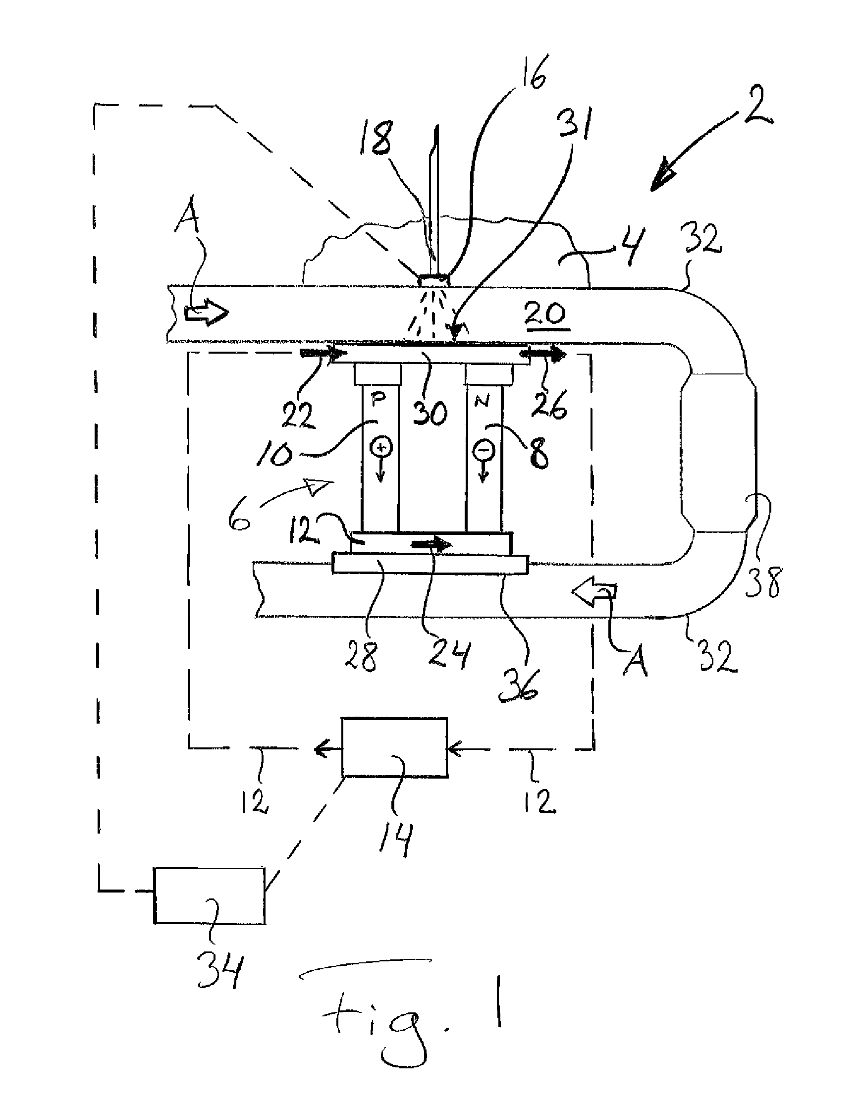
[0045]FIG. 2 depicts schematically an exhaust post-treatment device 2 for a vehicle 4 according to the invention, which device 2 comprises a Peltier element 6. The device 2 comprises also a supply device 16 for supply to the exhaust gases 20 of liquid reducing agent 18 intended for reduction of nitrogen oxides present in them.

[0046]The embodiment depicted in FIG. 2 differs from that described with reference to FIG. 1 in that in this case the heat absorption side 28 of the Peltier element 6 is adjacent to the outside of an exhaust pipe 32, and that a possible catalyst 38 is provided downstream of the heat absorption side 28 of the Peltier element 6. The catalyst 38 may however also be situated upstream of the heat absorption side 28 of the Peltier element 6, as in FIG. 1, or alternatively the exhaust post-treatment device may be used with no catalyst. In other respects, the description with respect to FIG. 1 applies also, e.g. as regards a possible control unit, in FIG. 2.

third embodiment

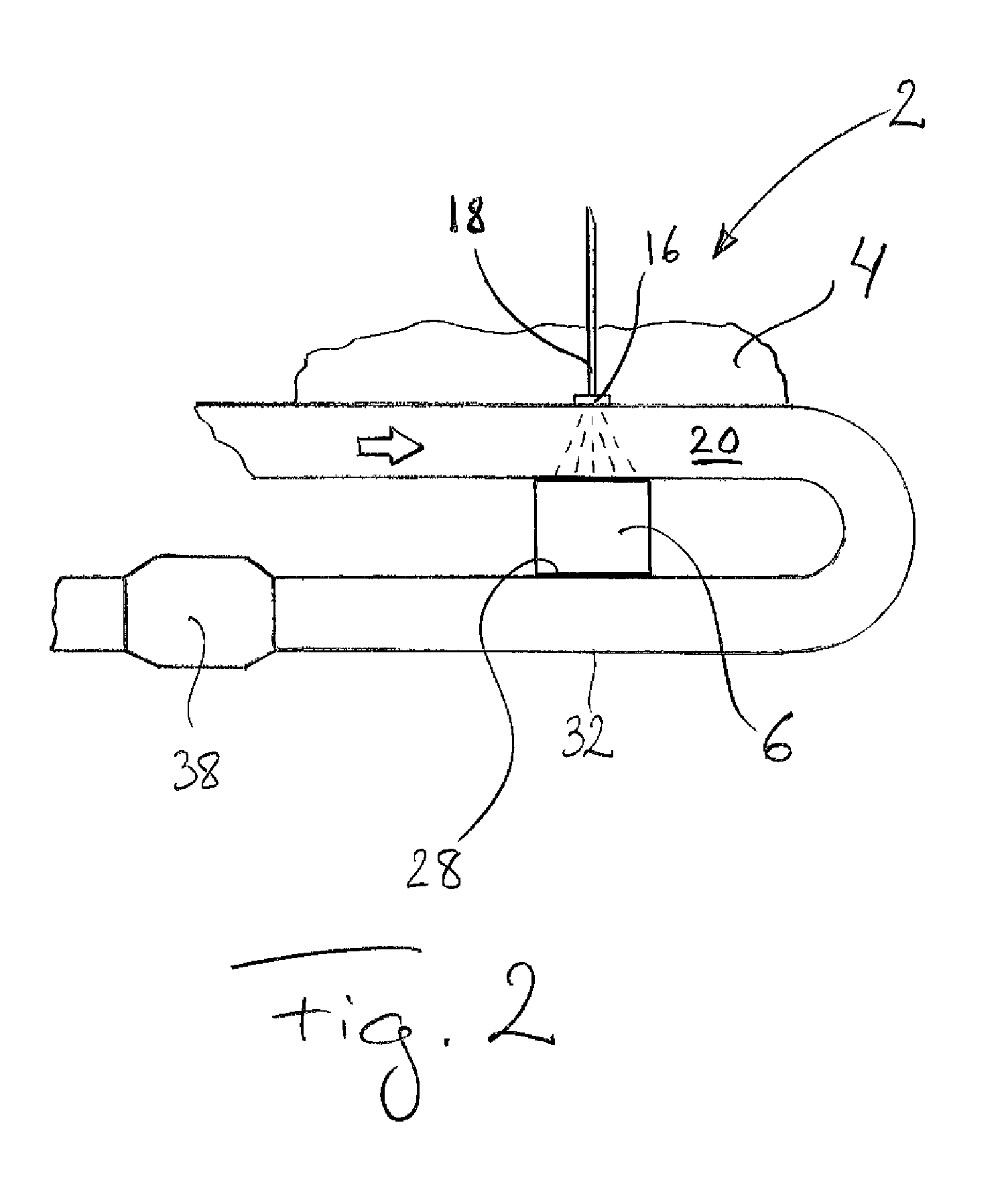
[0047]FIG. 3 depicts schematically an exhaust post-treatment device 2 for a vehicle 4 according to the invention, which device 2 comprises a Peltier element 6. The device 2 likewise comprises a supply device 16 for supply to the exhaust gases 20 of liquid reducing agent 18 intended for reduction of nitrogen oxides present in them.

[0048]The embodiment depicted in FIG. 3 differs from that described with respect to FIG. 1 in that in this case the heat absorption side 28 of the Peltier element 6 is upstream of the supply device 16 for supply of liquid reducing agent 18 to the exhaust gases 20. In other respects, the description with respect to FIG. 1 applies also, e.g. as regards a possible control unit, to the embodiment depicted in FIG. 2 but any catalyst 38 has to be situated downstream of the supply device 16 for supply of liquid reducing agent 18 to the exhaust gases 20.


PUM


Abstract

An exhaust post-treatment device (2) for a vehicle (4) for reducing nitrogen oxides present in the exhaust gases (20) of the vehicle (4) by supply of liquid reducing agent (18) to the exhaust gases (20) in an exhaust pipe (32). The device (2) locally warms a surface (31) within the exhaust pipe (32) by a Peltier element (6) by using thermal energy from the exhaust gases (20) to vaporize liquid reducing agent (18) which reaches the surface (31), thereby avoiding the formation of deposits of reducing agent within the exhaust pipe (32). Also a method for post-treatment of exhaust gases from vehicles with an exhaust post-treatment device (2) including a Peltier element (6).

Description

CROSS-REFERENCE TO RELATED APPLICATIONS[0001]The present application is a 35 U.S.C. §§371 national phase conversion of PCT / SE2011 / 051244, filed Oct. 18, 2011, which claims priority of Swedish Application No. 1051161-6, filed Nov. 8, 2010, the contents of which are incorporated by reference herein. The PCT International Application was published in the English language.FIELD OF THE INVENTION[0002]The invention relates to an exhaust post-treatment device for a vehicle and a method for post-treatment of exhaust gases from vehicles.BACKGROUND TO THE INVENTION AND PRIOR ART[0003]In diesel vehicles, particularly in heavy vehicles such as heavy trucks, the SCR method, i.e. a method for selective reduction of nitrogen oxides, is used to clean the vehicle's exhaust gases so that those released into the surroundings do not contain high contents of nitrogen oxides.[0004]In the SCR method, a liquid urea solution injected into the exhaust pipe may be used as NOx reducing agent.[0005]Using liquid...

Claims


Application Information

Patent Timeline
Patent Type & Authority Patents(United States)
IPC IPC(8): F01N3/00F01N3/20F01N3/18
CPCF01N3/18F01N3/206F01N3/2066F01N2240/02F01N2610/02F01N2610/102F01N2240/16Y02T10/24Y02T10/12Y02A50/20F01N3/20F01N9/00F01N13/08
Inventor LOMAN, PETERHALL, OLARYRFELDT, DANIEL
Owner SCANIA CV AB
Why Eureka
Try Eureka