
Electric device and a method for a wave power plant

a wave power plant and electric device technology, applied in the direction of electric generator control, process and machine control, instruments, etc., can solve the problem of high dampening of the generator, and achieve the effect of easy adaptation to supply energy

Active Publication Date: 2015-06-02
SEABASED LTD
View PDF55 Cites 1 Cited by
  • Summary
  • Abstract
  • Description
  • Claims
  • Application Information

AI Technical Summary

Benefits of technology

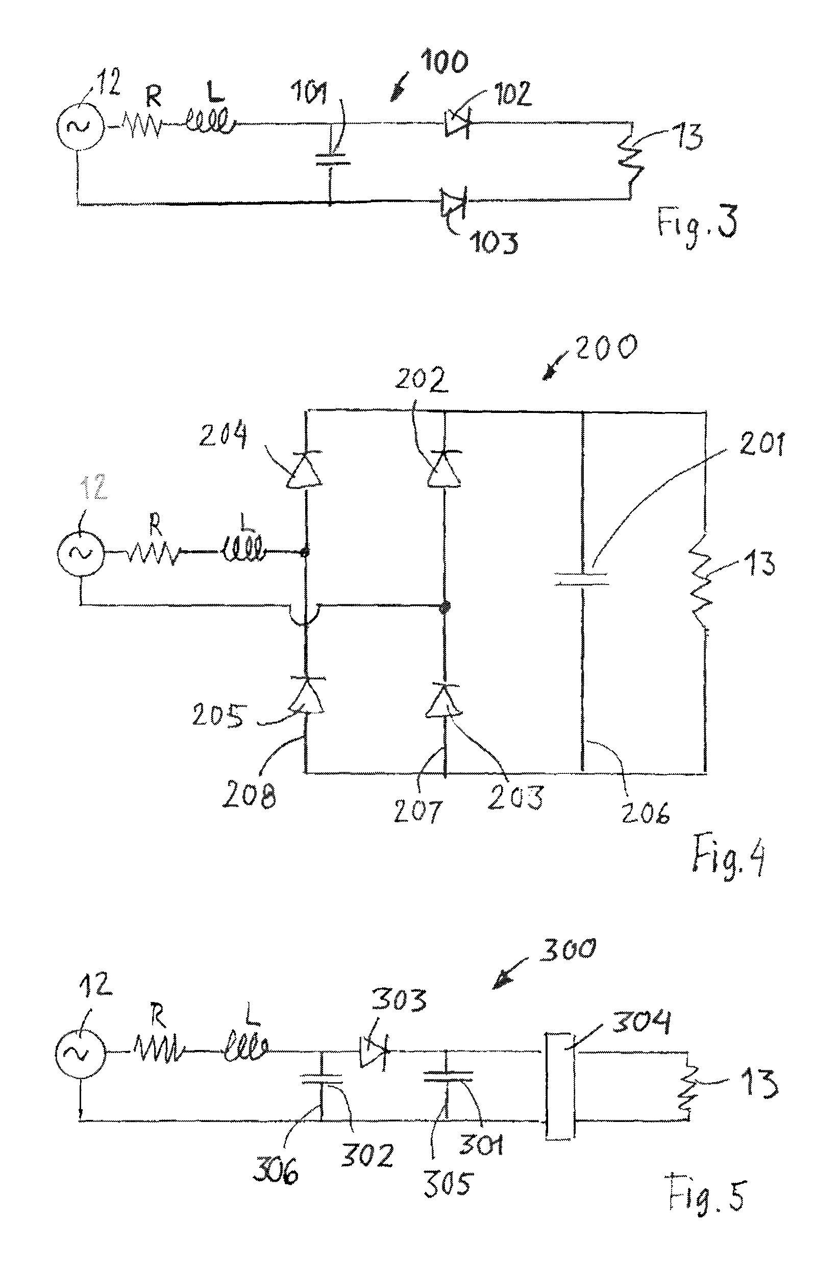
The patent describes a method for improving the power capture ratio of a system by using a bridge circuit to create resonance. This resonance results in a high dampening of the generator, which can be either used as active power or directed to the load to make use of the reactive power. The layout of the bridge circuit is designed to efficiently transfer power from reactive power to active power, making it easier to supply energy to the grid. Overall, the patent offers an effective and simpler alternative to mechanical measures for creating resonance.

Problems solved by technology

The resonance also results in a high dampening of the generator.

Method used


Image

  • Electric device and a method for a wave power plant
  • Electric device and a method for a wave power plant
  • Electric device and a method for a wave power plant

Examples


Embodiment Construction

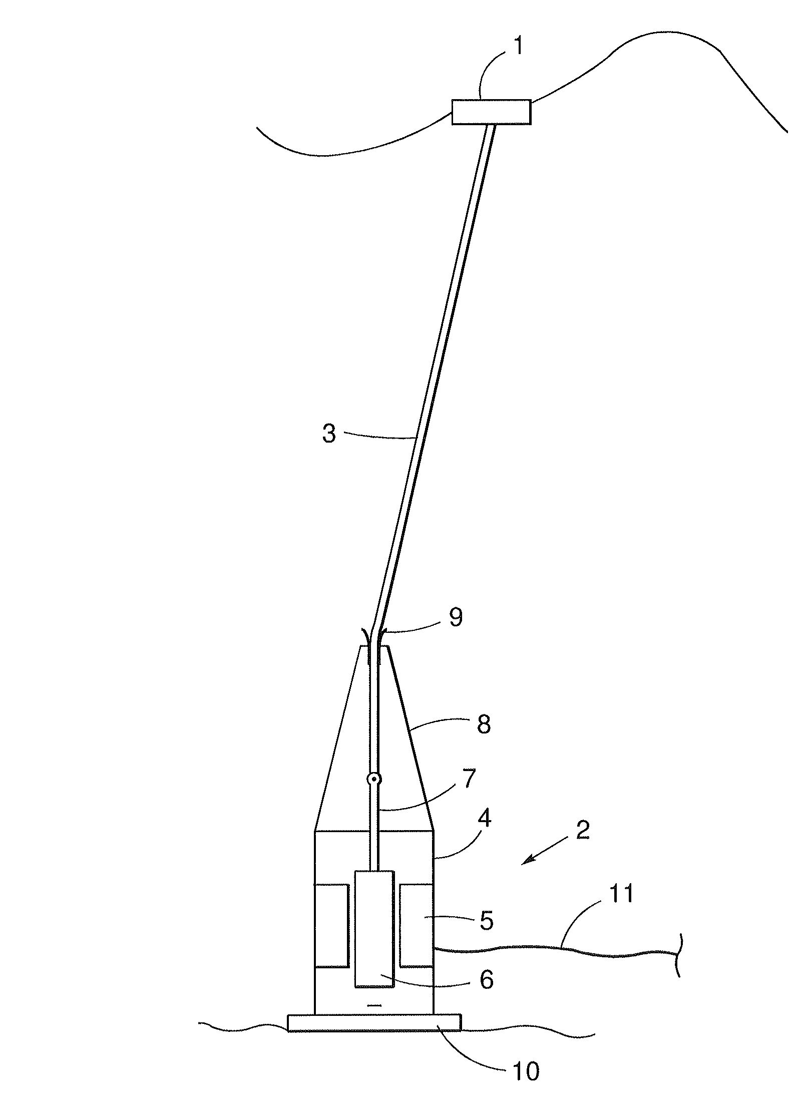
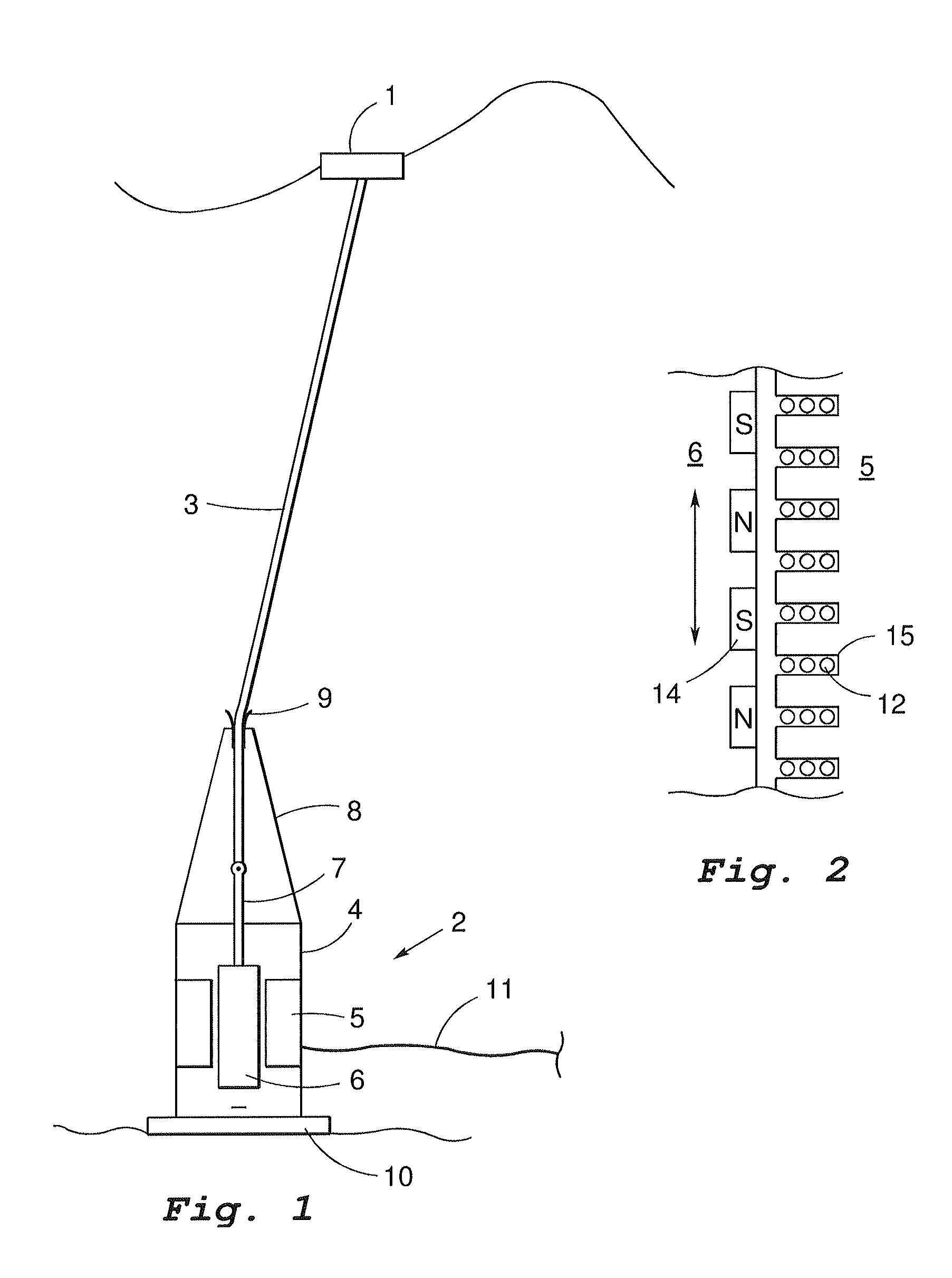
[0044]FIG. 1 is a schematic side view of an electric device according to the invention, adapted as a wave power unit in operation in the sea. A floating body 1 floats on the sea surface and is connected by a connection means 3 such as a cable, wire, rope, chain or the like, to a linear generator 2 anchored at the sea bed. In the figure the generator is attached at the sea bed. It is, however, to be understood that the generator can be located above the sea bed and be anchored in some other way.

[0045]The linear generator 2 has a stator 5 with winding and a translator 6 with magnets. The translator 6 is able to reciprocate up and down within the stator 5 thereby generating current in the stator winding, which current by an electric cable 11 is transferred to an electric network.

[0046]The translator 6 includes a rod 7 to which the wire 3 is attached. When the floating body 1 due to the wave movements of the sea surface is forced to move up the floating body will pull the translator 6 u...


PUM


Abstract

The invention relates to an electric device with a winding (12) and means for inducing a current in the winding. A bridge circuit (400) electrically connects the winding (12) to a load (13). According to the invention the bridge circuit (400) includes capacitor means (401, 402), which is adapted for obtaining resonance with the impedance of the winding (12).

Description

FIELD OF INVENTION[0001]The present invention in a first aspect relates to an electric device including a winding, means for inducing a current in the winding and an electrical bridge circuit with capacitor means. The invention also relates to a wave power plant including a plurality of such electric devices and to an electric network connected to at least one such electric device.[0002]In a second aspect the invention relates to a use of such an electric device.[0003]In a third aspect the invention relates to a method for controlling an electric winding in which a current is induced.BACKGROUND OF INVENTION[0004]Wave movements in the sea and in large inland lakes constitute a potential source of energy that has scarcely been exploited so far. However various suggestions have been made to use the vertical movements of the sea for producing electrical power in a generator. Since a point on the sea surface makes a reciprocating vertical movement it is suitable to use a linear generator...

Claims


Application Information

Patent Timeline
Patent Type & Authority Patents(United States)
IPC IPC(8): F03B13/10F03B13/12H02P9/04H02P9/00F03B13/18F03B15/00H02M7/10H02P9/48
CPCH02M7/103F03B13/1845F03B15/00H02P9/48F03B13/18F05B2220/707Y02E10/38H02P2101/10H02P9/02Y02E10/30
Inventor LEIJON, MATSBOSTROM, CECILIAERIKSSON, MIKAEL
Owner SEABASED LTD
Learn More