Method and a user interaction system for controlling a lighting system, a portable electronic device and a computer program product

a technology of user interaction and lighting system, applied in the direction of electric variable regulation, process and machine control, instruments, etc., can solve the problems of complex lighting system, difficult for users to assess which effects are available in specific areas, etc., and achieve the effect of convenient evaluation for users

Active Publication Date: 2015-05-26
KONINKLIJKE PHILIPS ELECTRONICS NV
View PDF13 Cites 8 Cited by
  • Summary
  • Abstract
  • Description
  • Claims
  • Application Information

AI Technical Summary

Benefits of technology

[0007]The user interaction system provides the user information about the possible lighting effect that may be obtained at the specific location which is indicated by the location indication. This is user-friendly because the user knows a priori, before providing input related to a desired lighting effect, what effects may be obtainable for the specific location. Therefore, the user does not have to discover through trial-and-error whether the effect he has in mind is obtainable. Thus, the user will not select an unobtainable effect and will not be disappointed by the lighting system. Lighting systems become much more complex and a surface or an area of the environment is often lit by a plurality of controllable light sources and, thus, the lighting effect is the combination of a plurality of lighting effects of individual controllable light sources. It is to be noted that the at least two controllable light sources which contribute to the obtainable lighting effect have to emit light to obtain the obtainable lighting effect. Especially the more intensive use of individually controllable light sources like, for example, individually controllable Light Emitting Diodes, makes it much more difficult for users to assess which effects are obtainable in specific areas. The system is capable of analyzing the lighting effects of a plurality of controllable light sources on the basis of the lighting system model and translates the lighting effects of controllable individual light sources to lighting effects for the specific location. Thus, the system performs the translation from “what are the capabilities of the lighting system” to “which effect is obtainable at the indicated location”. As a result, the user needs to have less knowledge about the functioning of lighting systems in general, and the lighting system of the environment in particular.
[0012]In an embodiment, the means for receiving a location indication is a user-input means for receiving user-input comprising the location indication. It is more user-friendly if the user selects the location indication himself. The system then provides the obtainable effect for a location of which the user wants to know the obtainable effect.
[0019]In another embodiment, the overlay image creator is further configured to generate the overlay image, which comprises information which presents the changed operation of the controllable light source of the lighting system in accordance with the generated control signal. Thus, in other words, the overlay image is a virtual addition to the reality of the subarea image, which shows the user what the subarea is going to look like when the lighting system is controlled with the control signal. This allows the user to evaluate the lighting situation that may arise from controlling the lighting system with the generated control signal, even before the lighting system is controlled with the control signal. It is convenient for the user to evaluate the controlling of the lighting system in a virtual environment, because it allows the design of a lighting control pattern without using the lighting system and, thus, the lighting system is not unnecessarily occupied for designing the lighting control pattern.
[0021]In a further embodiment, the overlay image creator is configured to generate the overlay image which comprises feedback about the feasibility of the desired lighting effect or the desired lighting effect change. As mentioned before, the light effect controller may be unable to control the lighting system such that the desired light effect or the desired light effect change is obtained, because of limitations of the lighting system. The overlay image may provide feedback to the user, which indicates to which extent the desired light effect is obtainable and to which extent the desired light effect change is obtainable, in other words, the feedback presents how feasible the desired light effect or light effect change is, given the lighting system present in the environment. In general this is perceived as user-friendly because it makes the user aware of limitations of the lighting system and the user is not unexpectedly disappointed if the lighting system is controlled with the control signal.
[0028]Especially in cases where the location indication is provided to the user interaction system as a position in the subarea image, the user interaction system has to know which specific subarea is recorded in the subarea, so that the location identification means is capable of detecting which specific location in the environment matches with the location indication. The embodiment provides means to detect, while obtaining a recording of the subarea via the camera, to which part of the environment the camera is directed and which part of the environment is recorded by the camera. This is very user-friendly because the user interaction system is capable of automatically detecting which specific location is indicated in the subarea image, without requiring additional user interaction.
[0036]The portable electronic device, the method of controlling the lighting system and the computer program product provide the same benefits as the user interaction system according to the first aspect of the invention and have similar embodiments with similar effects as the corresponding embodiments of the system.

Problems solved by technology

Lighting systems become much more complex and a surface or an area of the environment is often lit by a plurality of controllable light sources and, thus, the lighting effect is the combination of a plurality of lighting effects of individual controllable light sources.
Especially the more intensive use of individually controllable light sources like, for example, individually controllable Light Emitting Diodes, makes it much more difficult for users to assess which effects are obtainable in specific areas.

Method used


Image

  • Method and a user interaction system for controlling a lighting system, a portable electronic device and a computer program product
  • Method and a user interaction system for controlling a lighting system, a portable electronic device and a computer program product
  • Method and a user interaction system for controlling a lighting system, a portable electronic device and a computer program product

Examples


Embodiment Construction

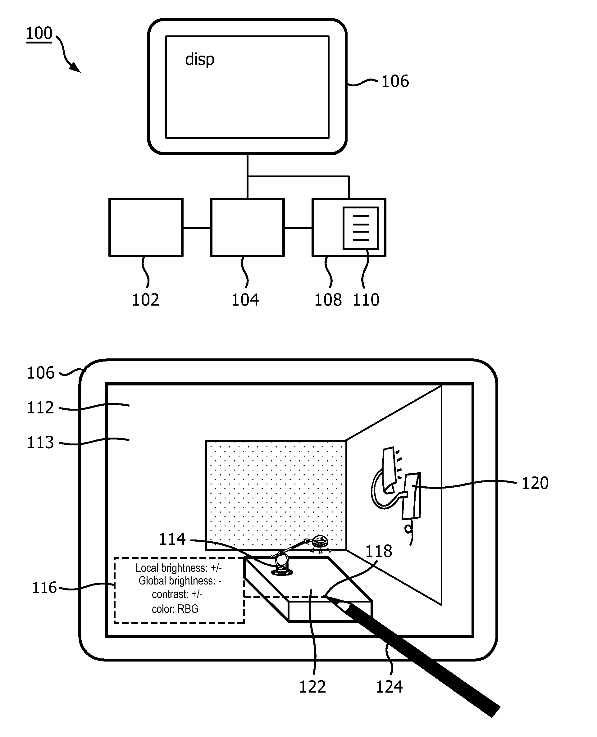
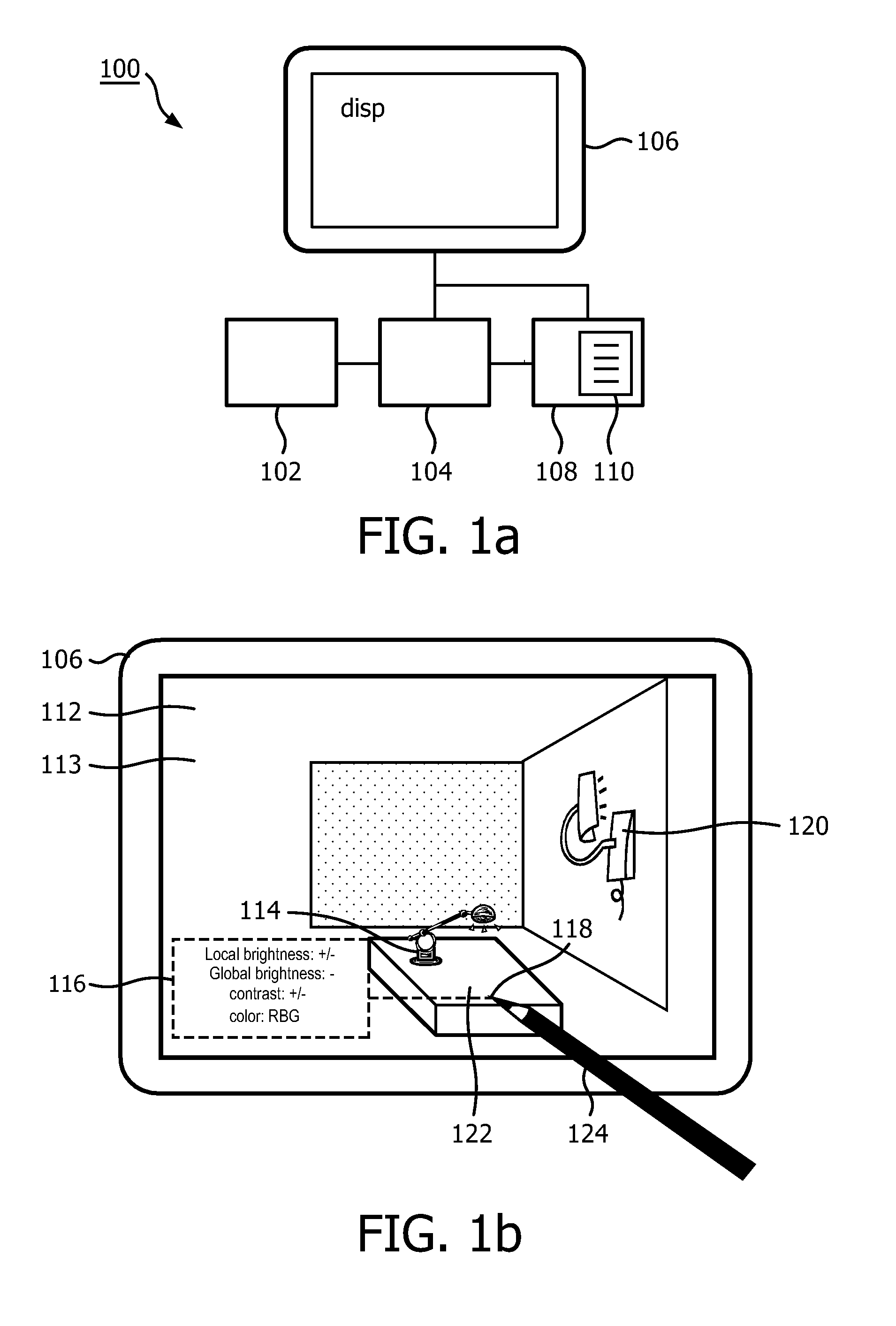
[0051]A first embodiment of a user interaction system 100 according to the first aspect of the invention is shown in FIG. 1a. By means of the user interaction system 100, a lighting system for lighting an environment may be controlled. The user interaction system 100 comprises a display 106, an input means 102, a location identification means 104 and an overlay image creator 108. The display is capable of displaying a subarea image 112 and an overlay image 113, which are shown in FIG. 1b. The subarea image 112 may be displayed without the overlay image 113 and together with the overlay image 113. The subarea image 112 is a recording of a specific subarea of the environment and the subarea image 112 is recorded at a specific moment in time. The user-input means 102 is for receiving user input. The user input comprises a location indication 118. The location indication 118 may initially relate to a point or location in the subarea image 112 or may initially relate to a point or locati...


PUM


Abstract

The invention provides a user interaction system (100) and a method of controlling a lighting system. The user interaction system (100) comprises a display (106), a means for receiving a location indication (102), a location identification means (104) and an overlay image creator (108). The display (106) displays a subarea image and an overlay image. The subarea image is an image of a specific subarea of the environment. The location identification means (104) detects which specific location in the environment is indicated by the location indication. The overlay image creator (108) generates the overlay image. The overlay image comprises information related to a lighting effect which is obtainable by the lighting system at the specific location. The obtainable effect is an effect of at least two controllable light sources of the lighting system. The information which is related to the obtainable lighting effect is based on a lighting system model (110) which represents effects that are obtainable in the environment by controllable light sources of the lighting system.

Description

FIELD OF THE INVENTION[0001]The invention relates to user interaction systems for controlling lighting systems.BACKGROUND OF THE INVENTION[0002]Published patent application WO 2010 / 079400 discloses a control system for controlling one or more light sources. The system comprises an image sensor array for obtaining a scene image of a scene. The light emitted by the light sources comprises for each one of the light sources a unique code. The codes are detected by the system. In this way the system obtains knowledge about the available light sources in the environment and a footprint of each one of the light sources. The system presents the scene image to a user on a display and accompanies the scene image with a control image in which control items are shown. The control items are related to the recognized light sources in the scene and the user may select via the respective control items a specific operational mode for the respective light sources. The scene image may be updated to sh...

Claims


Application Information

Patent Timeline
Patent Type & Authority Patents(United States)
IPC IPC(8): G09G5/00G06F3/01G06T11/60H05B37/02
CPCH05B37/0245G06F3/011G06T11/60H05B37/0272H05B37/029H05B47/155H05B47/19H05B47/175
Inventor ALIAKSEYEU, DZMITRY VIKTOROVICHMASON, JONATHAN DAVIDENGELEN, DIRK VALENTINUS RENEWEDA, JOHANNESVAN DE SLUIS, BARTEL MARINUS
Owner KONINKLIJKE PHILIPS ELECTRONICS NV
Why Eureka
Try Eureka