
Connection structure, connection method and differential signal transmission cable

a technology of connection structure and transmission cable, which is applied in the direction of cable termination, final product manufacturing, sustainable manufacturing/processing, etc., can solve the problems of difficult to meet the recent needs of further improvement of transmission characteristics, thus deteriorating transmission characteristics, etc., to prevent the deterioration of transmission characteristics, prevent deformation and melting

Active Publication Date: 2015-05-19
HITACHI METALS LTD
View PDF10 Cites 61 Cited by
  • Summary
  • Abstract
  • Description
  • Claims
  • Application Information

AI Technical Summary

Benefits of technology

[0033]According to one embodiment of the invention, a connection structure can be provided that can prevent the deterioration of the transmission characteristics by preventing the deformation and melting of an insulation during the solder connection work, as well as a connection method and a differential signal transmission cable.

Problems solved by technology

In the method of directly connecting the outer conductor to the ground electrode on the substrate using the solder, there is a problem that an insulation inside the cable is deformed or melted by thermal stress or heat during solder connection work and transmission characteristics thus deteriorate.
In the method of connecting the drain wire to the ground electrode of the substrate using the solder, there is a problem that it is difficult to meet the recent needs of further of improvement in transmission characteristics since transmission characteristics deteriorate due to deformation of the insulation caused by the drain wire.

Method used


Image

  • Connection structure, connection method and differential signal transmission cable
  • Connection structure, connection method and differential signal transmission cable
  • Connection structure, connection method and differential signal transmission cable

Examples


examples

[0128]A connecting member having a recessed shape (Example 1) and a connecting member having a trough shape (Example 2) as the first embodiment of the invention and a connecting member having a plate shape (using a jig) (Example 3) as the second embodiment of the invention were solder-connected to respective outer conductors, and an amount of collapse of an insulation (core) and variation in impedance were measured. Meanwhile, as a connection structure of the conventional technique, an outer conductor was directly soldered without using a connecting member (Comparative Example 1), and an amount of collapse of an insulation (core) and variation in impedance were measured in the same manner.

[0129]FIG. 12A is a conceptual cross-sectional view showing Comparative Example 1 (a connection structure of a conventional technique) at the time of pressing by a soldering tool and FIG. 12B is a conceptual cross-sectional view showing Example 1 (the modification of the connection structure in the...


PUM

PropertyMeasurementUnit
widthaaaaaaaaaa
conductoraaaaaaaaaa
heightaaaaaaaaaa

Abstract

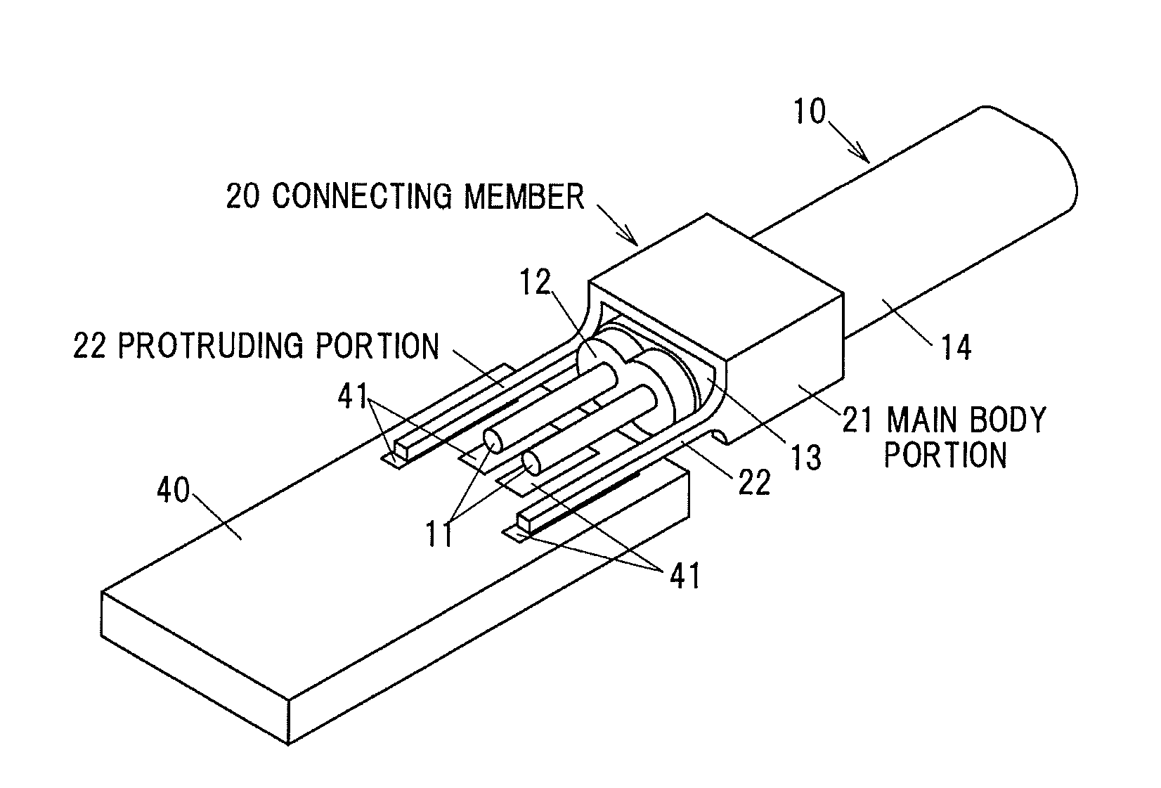
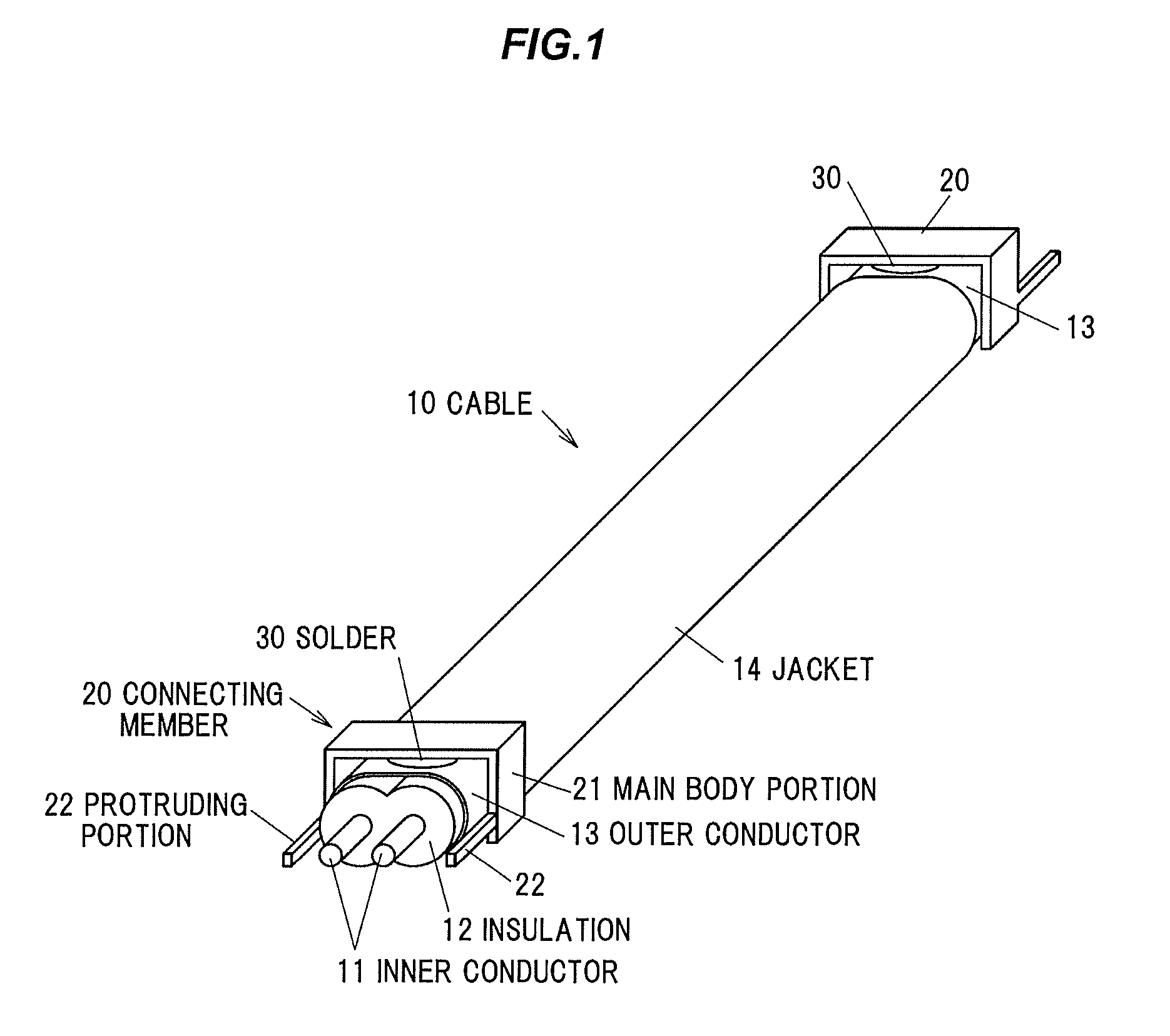
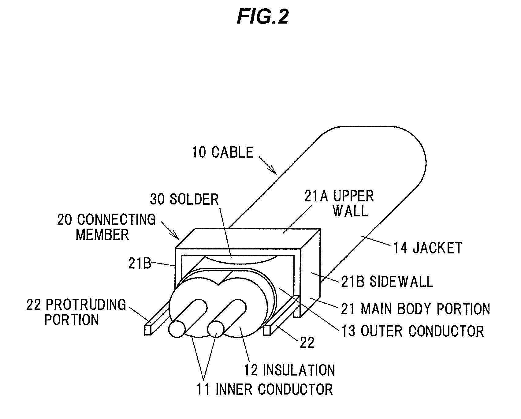
A connection structure for connecting an outer conductor of a differential signal transmission cable to a substrate includes a connecting member including a main body portion and a protruding portion protruding from the main body portion. The outer conductor is connected via the connecting member to the substrate. The connecting member is solder-connected to the outer conductor via the main body portion and is solder-connected to the substrate via the protruding portion.

Description

[0001]The present application is based on Japanese patent application No. 2011-285371 filed on Dec. 27, 2011, the entire contents of which are incorporated herein by reference.BACKGROUND OF THE INVENTION[0002]1. Field of the Invention[0003]The invention relates to a connection structure between a differential signal transmission cable and a substrate, a connection method for connecting a differential signal transmission cable to a substrate, and a differential signal transmission cable.[0004]2. Description of the Related Art[0005]In connecting a differential signal transmission cable to a substrate, it is necessary to connect an outer conductor exposed at an end portion of the cable to a ground electrode on the substrate for grounding.[0006]As a method of connecting the outer conductor to the ground electrode on the substrate, there is a method in which the outer conductor is directly connected to the ground electrode on the substrate using a solder.[0007]On the other hand, there is...

Claims


Application Information

Patent Timeline
Patent Type & Authority Patents(United States)
IPC IPC(8): H01R9/05H05K1/18H05K3/34
CPCH05K1/18H05K3/3405H05K2201/1031H05K2201/1034H05K2201/10356Y10T29/49149Y02P70/50
Inventor KODAMA, SOHEITANAKA, KOTARO
Owner HITACHI METALS LTD
Learn More