
Support for solar energy collectors

a solar energy collector and support technology, applied in the field of solar energy systems, can solve problems such as interference with installation, and achieve the effects of reducing the cost of constructing sun tracking solar collection systems, reducing mechanical complexity, and reducing costs

Active Publication Date: 2015-05-19
SUNPOWER CORPORATION
View PDF98 Cites 47 Cited by
  • Summary
  • Abstract
  • Description
  • Claims
  • Application Information

AI Technical Summary

Benefits of technology

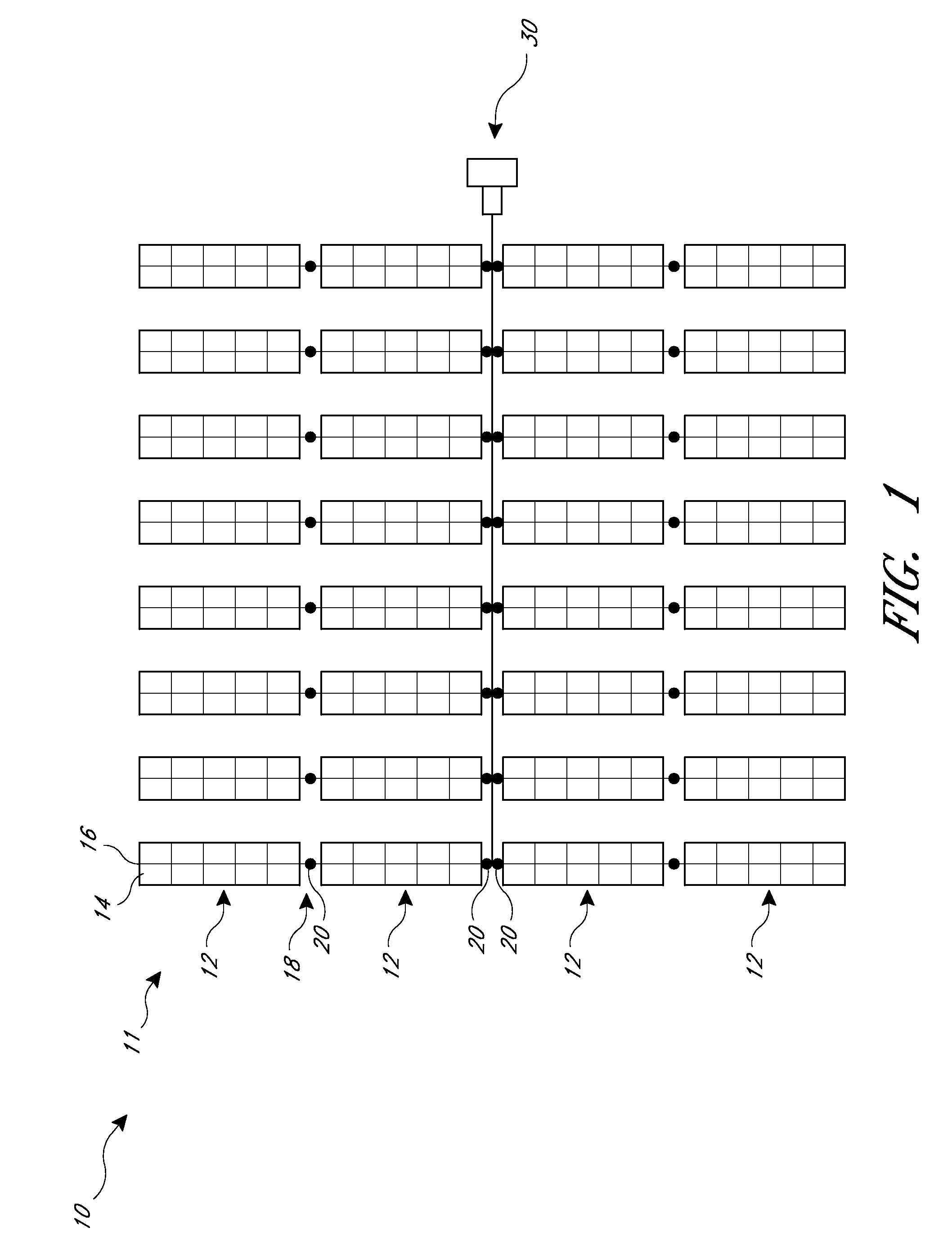
[0006]An aspect of at least one of the inventions disclosed herein includes the realization that costs for constructing sun tracking solar collection systems can be reduced by using bearings that are lower cost and less mechanically complex than a conventional roller bearing. For example, some solar systems are designed to pivot the solar collection devices over a range of motion of only about 30-60° for each side relative to a vertical alignment. Additionally, in some designs, the bearing supports for the torque tubes can be disposed between mounts of other devices that are connected directly to the torque tube. Such devices would normally would interfere with the installation of a typical roller bearing installation. Thus, a bearing that can be mated with a torque tube at a position between other components connected to it, such as mounts for solar collector devices that may be preinstalled at a factory, can help reduce the labor required for installing such solar systems.
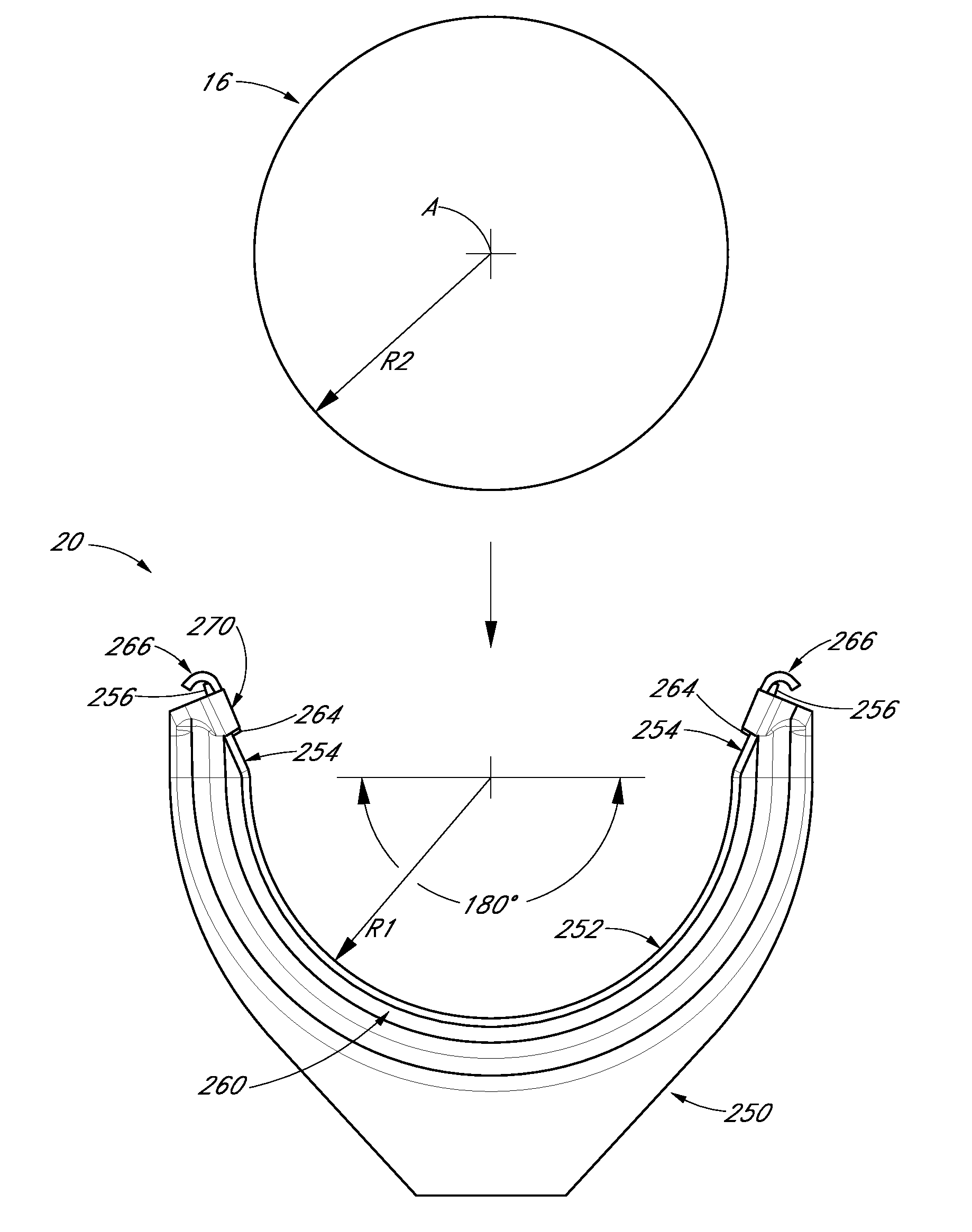
[0008]In accordance with another embodiment, a method of assembling a sun-tracking photovoltaic solar collector array can comprise mounting a first bearing housing at a position above the ground, inserting a first bearing member into the first bearing housing such that the first bearing member sags downwardly with first and second terminal ends of the first bearing member are spaced apart thereby having an upwardly facing bite, and lowering a torque tube such that a portion of the torque tube passes between the first and second terminal ends of the first bearing member and onto the bite of the first bearing member. The first bearing member can provide reduced friction with an outer surface of the torque tube such that the torque tube can pivot relative to the first bearing member, where the torque tube supports a plurality of photovoltaic devices.

Problems solved by technology

Such devices would normally would interfere with the installation of a typical roller bearing installation.

Method used


Image

  • Support for solar energy collectors
  • Support for solar energy collectors
  • Support for solar energy collectors

Examples


Embodiment Construction

[0031]The following detailed description is merely illustrative in nature and is not intended to limit the embodiments of the subject matter or the application and uses of such embodiments. As used herein, the word “exemplary” means “serving as an example, instance, or illustration.” Any implementation described herein as exemplary is not necessarily to be construed as preferred or advantageous over other implementations. Furthermore, there is no intention to be bound by any expressed or implied theory presented in the proceeding technical field, background, brief summary, or the following detailed description.

[0032]“Coupled”—The following description refers to elements or nodes or features being “coupled” together. As used herein, unless expressly stated otherwise, “coupled” means that one element / node / feature is directly or indirectly joined to (or directly or indirectly communicates with) another element / node / feature.

[0033]“Inhibit”—As used herein, inhibit is used to describe a r...


PUM

PropertyMeasurementUnit
angleaaaaaaaaaa
reduced frictionaaaaaaaaaa
frictionaaaaaaaaaa

Abstract

A solar energy collection system can include support devices made with bearings formed from sheet material. These bearings can be optionally formed so as to provide tool-less connections to their associated bearing housings. The bearings can be formed with an open configuration allowing a shaft to be inserted into an open bite of the bearing. Optionally, the bearing can be made from an ultrahigh molecular weight polyethylene plastic material. Additionally, two open-type bearing assemblies can be mounted axially offset and opposed to one another.

Description

TECHNICAL FIELD[0001]Embodiments of the subject matter described herein relate generally to solar energy systems which include supports for solar energy collecting devices.BACKGROUND[0002]Larger solar collector installations usually include an array of solar collector devices. Such systems can be used in conjunction with photovoltaic modules, thermal solar collector devices as well as concentrators for concentrating solar energy onto photovoltaic devices or thermal solar collection devices.[0003]Some of these solar collector installations include hardware for automatically adjusting the position of the collector devices to track the sun as it moves across the sky. This tracking movement can be accomplished in a number of different ways. Some systems use a single axis tracking system in which the collector devices pivot about a single axis. Such single axis type tracking systems often include a drive shaft or “torque tube” which defines a single pivot axis.[0004]Further, in some of t...

Claims


Application Information

Patent Timeline
Patent Type & Authority Patents(United States)
IPC IPC(8): H01L31/0203F24J2/54F24S23/70F24S50/20H01L31/042
CPCH02S20/00F24J2/541H02S20/10H02S20/32F24S30/425F24S2030/136F24S2030/15Y02E10/47Y02E10/52Y10T29/49826Y10T29/49863F16M11/00H01L31/042H01L31/18
Inventor BARTON, NICHOLAS
Owner SUNPOWER CORPORATION
Learn More