
Brake hose guide

a technology of brake hoses and guides, which is applied in the direction of braking systems, cycle equipment, machine supports, etc., can solve the problems of difficult to ensure a space for mounting the brake hose guides

Active Publication Date: 2015-05-19
HONDA MOTOR CO LTD
View PDF11 Cites 0 Cited by
  • Summary
  • Abstract
  • Description
  • Claims
  • Application Information

AI Technical Summary

Benefits of technology

[0007]The present invention has been made in view of the above-mentioned circumstances. It is an object of an embodiment of the present invention to provide a brake hose guide that can be mounted even when a mounting width is relatively narrow.
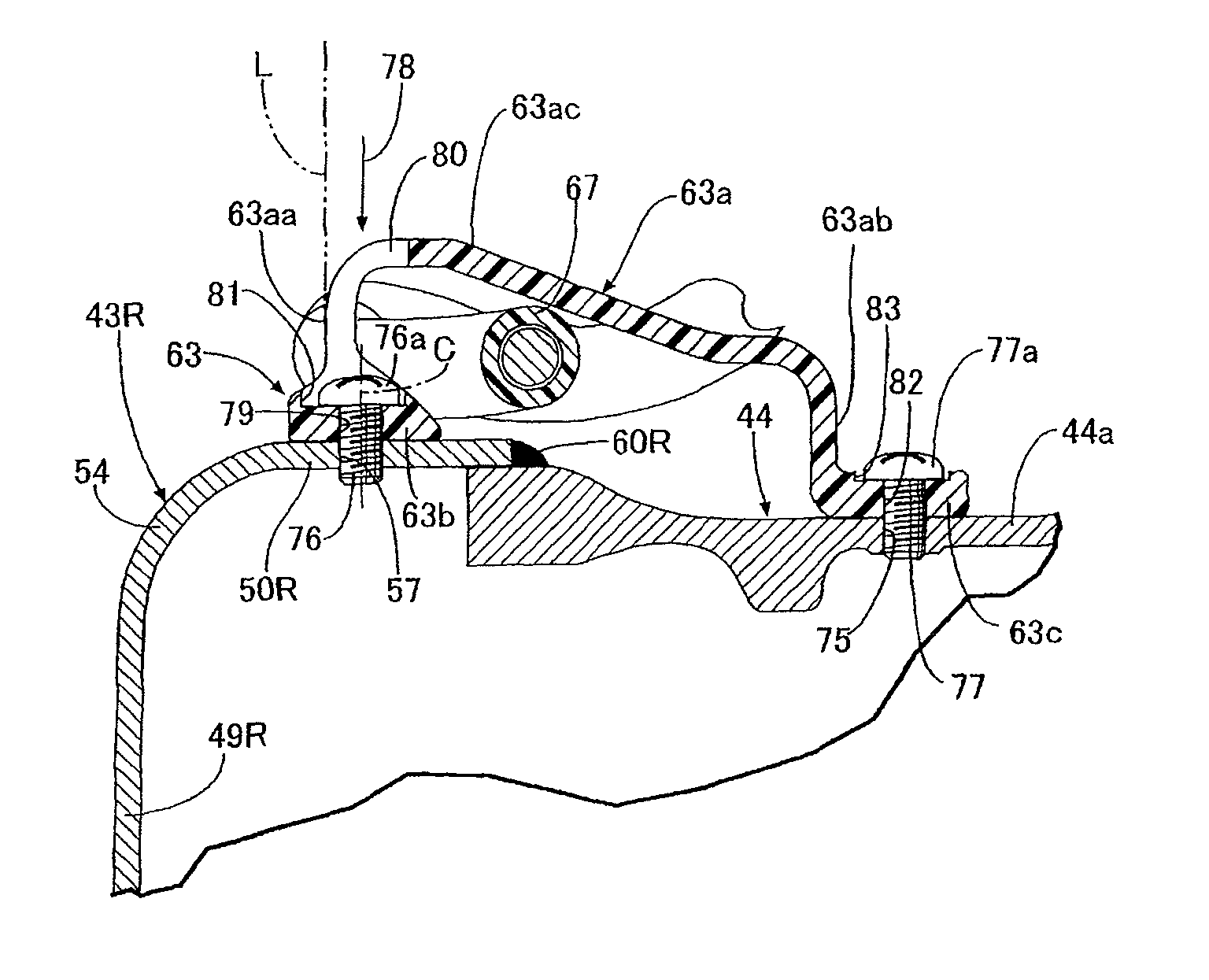
[0011]According to an embodiment of the present invention, a counterboring portion is coaxially and contiguously formed with the fastening hole for preventing an enlarged diameter head portion of the fastening member, that is allowed to pass through the fastening hole, from projecting toward the inside of the guide portion, formed in the mounting portion in such a manner that the counterboring portion accommodates the enlarged diameter head portion therein.
[0015]According to an embodiment of the present invention, the opening portion for allowing the fastening member to pass therethrough is formed on the guide portion on the extension of the center axis of the fastening hole. Accordingly, a fastening operation of the fastening member can be performed from the guide portion side in a state where the mounting portion is brought into contact with the support body. Thus, a brake hose guide mounting operation can be easily performed.
[0017]According to an embodiment of the present invention, the counterboring portion that is coaxially connected with the fastening hole is formed in the mounting portion in such a manner that the enlarged diameter head portion of the fastening member can be accommodated in the counterboring portion. Accordingly, it is possible to make the enlarged diameter head portion minimally injure the brake hose that is allowed to pass through the guide portion.
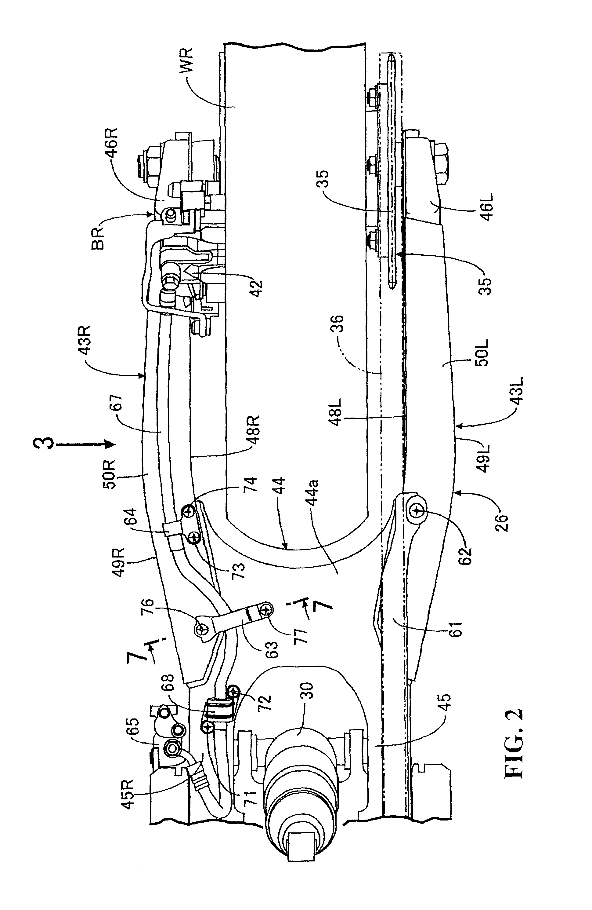
[0018]According to an embodiment of the present invention, the brake hose guide includes the mounting portion arranged on one side in the vehicle widthwise direction, and the second mounting portion arranged on the other side in the vehicle widthwise direction as integral parts thereof, and is mounted on the swing arm of the motorcycle. Accordingly, a support width of the brake hose can be broadened while decreasing a space necessary for mounting the brake hose guide on a swing arm side.

Problems solved by technology

When a distance between both mounting portions is narrow, a width of the guide portion also becomes narrow so that, depending on a shape of a swing arm, it is difficult to ensure a space for mounting the brake hose guide in the swing arm.

Method used


Image

  • Brake hose guide
  • Brake hose guide
  • Brake hose guide

Examples


Embodiment Construction

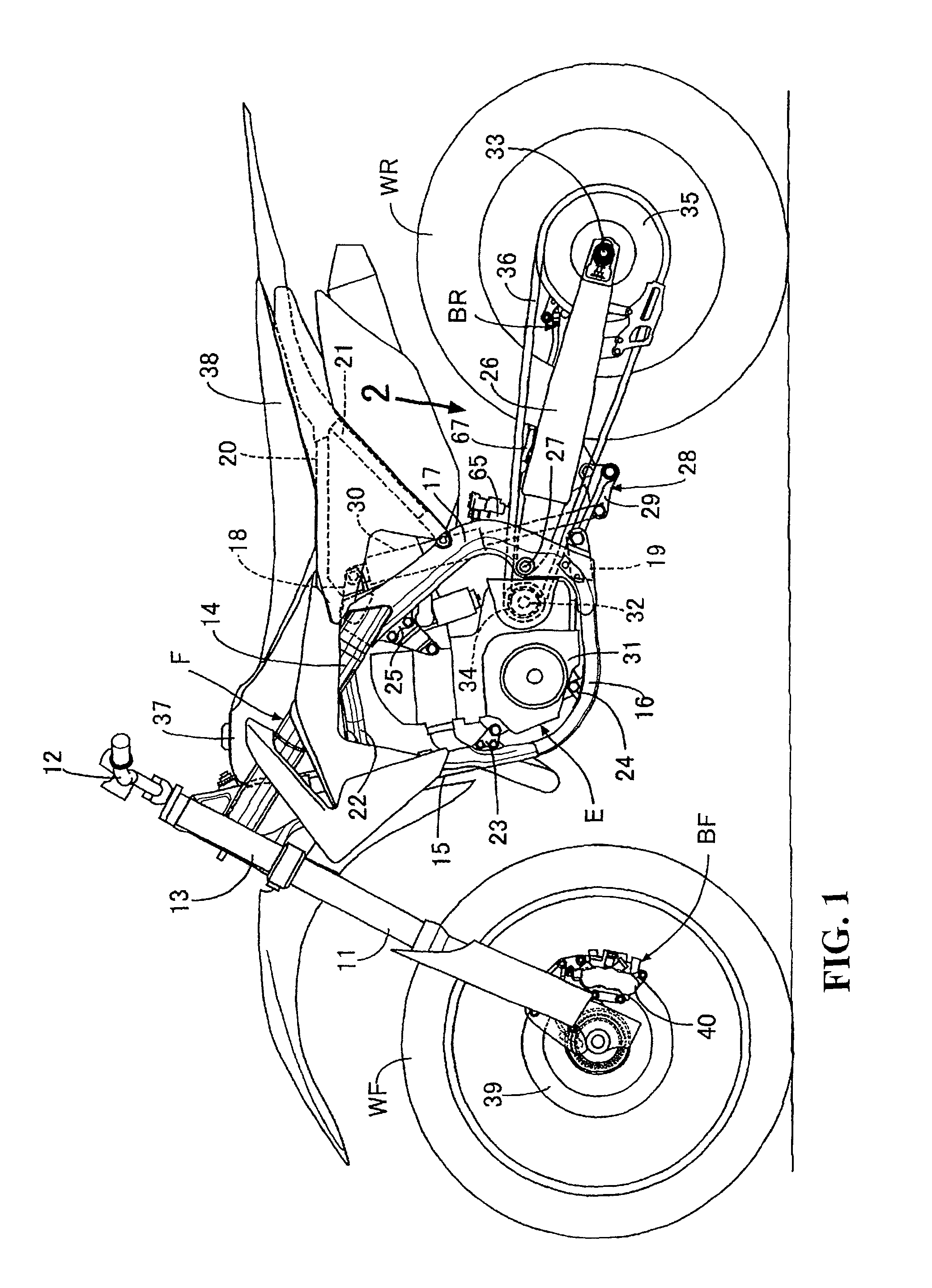
[0029]An embodiment of the present invention is explained in conjunction with FIG. 1 to FIG. 8. In the explanation made hereinafter, the frontward and rearward directions, the upward and downward directions, and the leftward and rightward directions are directions as viewed from a rider who rides on a motorcycle.

[0030]As illustrated in FIG. 1, a miniaturized vehicle is a motocross motorcycle. A vehicle body frame F of the motorcycle includes a head pipe 13 for supporting a front fork 11 that pivotally supports a front wheel WF and a bar-shaped steering handle 12 in a steerable manner. A pair of left and right main frames 14 are provided extending in the rearward and downward direction from the head pipe 13. A down frame 15 extends in the rearward and downward direction from the head pipe at a steeper angle than the main frames 14. A pair of left and right lower frames 16 is connected to a lower end portion of the down frame 15 and extend in the rearward direction. A pair of left and...


PUM


Abstract

A brake hose guide includes a guide portion constructed of a pair of vertical wall portions with a connecting portion for connecting the vertical wall portions to each other. The brake hose guide is fastened to a support body for allowing a brake hose to pass through the inside of the guide portion. A mounting portion is connected to a specified vertical wall portion that constitutes at least one of the pair of vertical wall portions and is formed such that a portion of the mounting portion projects more toward the inside of the guide portion than the specified vertical wall portion. At least a portion of a fastening hole, that is formed in the mounting portion so as to allow a fastening member to pass therethrough, is arranged inside an outer end portion of the specified vertical wall portion as viewed from the fastening direction toward the support body.

Description

CROSS-REFERENCE TO RELATED APPLICATIONS[0001]The present application claims priority under 35 USC 119 to Japanese Patent Application No. 2011-185685 filed Aug. 29, 2011 the entire contents of that are hereby incorporated by reference.BACKGROUND OF THE INVENTION[0002]1. Field of the Invention[0003]The present invention relates to a brake hose guide that includes a guide portion formed of a pair of vertical wall portions and a connecting portion that is arranged between these vertical wall portions and connects these vertical portions. The brake hose guide is fastened to a support body in a state where a brake hose is allowed to pass through the inside of the guide portion.[0004]2. Description of Background Art[0005]A structure is disclosed in JP-A-2001-354183 wherein a wheel brake is mounted on a rear wheel that is pivotally supported on a rear portion of a swing arm of a motorcycle. A brake hose for supplying a liquid pressure to the wheel brake is arranged along an upper surface of...

Claims


Application Information

Patent Timeline
Patent Type & Authority Patents(United States)
IPC IPC(8): B62K11/00F16L3/00B60T17/04
CPCB60T17/046B62J11/16B62K25/283
Inventor KUWABARA, NAOKI
Owner HONDA MOTOR CO LTD
Learn More