Surface covering kit comprising panels and an extraneous locking element

a technology of locking element and surface covering, which is applied in the direction of sheet joining, flooring, fastening means, etc., can solve the problems of difficult machineability of many different surfaces, inability to work well, and inability to meet the needs of large-scale production, so as to improve the state of the art, improve the effect of quality and reliability

Inactive Publication Date: 2015-05-19
I TECONSULT
View PDF20 Cites 3 Cited by
  • Summary
  • Abstract
  • Description
  • Claims
  • Application Information

AI Technical Summary

Benefits of technology

[0018]It is an object of the present invention to improve the state of the art by providing simple, reliable, durable and cheap coupling means which are easily manufactured and especially well suited for thin panel geometries.

Problems solved by technology

This is often necessary because connection means that work well on a relatively short side (e.g. the transversal side of flooring panels) do not necessarily work well on distinctly longer sides (e.g. the longitudinal sides of flooring panels) and vice versa.
Such geometries with many different surfaces are difficult to machine and require several milling tools and milling passes.
It is very expensive to maintain milling tools for such complicated profiles with many surfaces over time because the necessary tight tolerances can not be met if the milling tools wear over time.
Constant maintenance and replacement of tools as well as the stopping of production facilities for maintenance is cost intensive.
Above this, in order to mill such profiles on the transverse sides, a portion of the material of a panel is milled away and thus lost if it cannot readily be recycled.
In the case of most wood based materials (such as MDF, HDF, chip boards and OSB boards) not only the wooden material is lost, but often also components of a chemical binder (resin or the like) are milled to a potentially hazardous and flammable fine dust which may be difficult and costly to dispose of.
Another disadvantage of such prior art is that such complicated profiles cannot be employed on relatively thin panels.
With such a tongue- and groove system on the transversal sides, a long and thin lever is left at the short ends of panels, which is easily damaged or broken off during transportation and during installation.
A further disadvantage of the above prior art is that such profiles demand some amount of overlapping of two panels on the transverse side.
While this overlapping portion may seem to be only a small percentage of the overall surface of a panel, it is a waste which translates directly into higher costs for customers.
A basic problem which arises from connections with dovetail like grooves such as in DE'016, is that they require undercuts.
Such undercuts are difficult to mill and again require a set of several different milling tools and techniques with a set of different corresponding cutting surfaces which must be aligned relative to each other and thus the tools need to be maintained regularly in order to keep tolerances.
A relatively high amount of defective products may also be a further consequence of such complex profiles.
As with the other prior art further above, they are relatively complex and expensive to produce.
A further disadvantage of DE'016 is that the disclosed dovetail shaped connecting element may be difficult to insert into its groove due to friction.
While the amount of friction on a relatively short transverse side of a panel may not pose a problem to manual insertion, the amount of friction on a standard length flooring panel (1300 mm) renders the dovetail shaped connecting element of DE'016 unusable on longitudinal sides of standard flooring panels.
Another disadvantage from DE'016 arises when a large load (such as heavy furniture) is placed on one panel next to another panel which carries no load at all.
The shape and the dimensions of the dovetailed connecting element of DE'016 are not well suited to efficiently counteract such rotational forces.
Such profiles may be achieved by broaching or by laser cutting according to EP'670, two methods known to be tedious, slow and expensive.
The only profile mentioned in EP'670 which could be achieved by traditional methods such as milling, is not well suited for reliable connections.
It cannot accommodate large separative forces, neither in horizontal, vertical, nor in rotational directions.

Method used


Image

  • Surface covering kit comprising panels and an extraneous locking element
  • Surface covering kit comprising panels and an extraneous locking element
  • Surface covering kit comprising panels and an extraneous locking element

Examples


Embodiment Construction

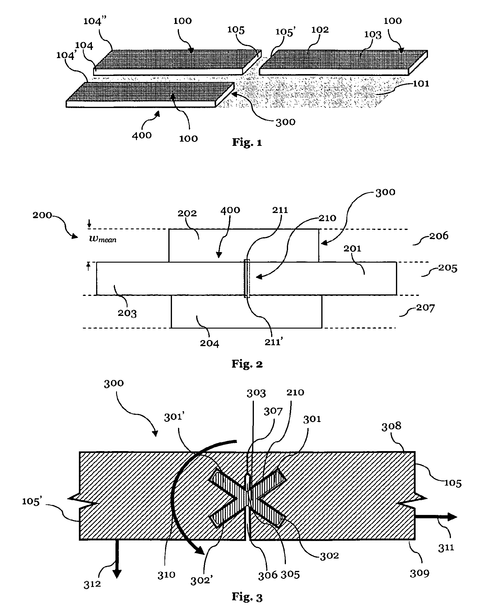
[0083]FIG. 1 is a schematic illustration showing three exemplary panels 100 laid in a common plane 101. These panels 100 can be made of any suitable material, however the invention is especially well suited for laminate panels made from HDF, MDF or LDF. The panels 100 can also be made of a wood composite, real wood, veneer, chip boards or OSB. The panels 100 have a mean or average thickness in between 3 mm and 30 mm and most preferably in between 4 mm and 14 mm. Since the connecting elements on the transverse sides according to the present invention have such a simple geometry, they are exceptionally well suited for very thin panels, such as 5 mm flooring laminate.

[0084]A decor 103 can either be provided as a separate decor layer, e.g. a decor printed on paper, or can be directly printed onto the panels 100. The decor 103 can be for example: a real wood imitation, a stone imitation, a ceramic imitation or the like.

[0085]As one can see in FIG. 1, each panel 100 defines a panel plane ...


PUM


Abstract

A surface covering kit is disclosed, comprising a plurality of generally rectangular panels (100). Each panel is provided with grooves (301, 302, 301′, 302′) forming an insertion channel (303) when two panels (100) are laid next to each other along their transverse sides (105, 105′) in a common laying plane (101). An extraneous locking element (210) is received by the insertion channel (303), the extraneous locking element (210) having a longitudinal dimension and a cross-section perpendicular to said longitudinal dimension which forms a cross with at least four cross arms. The corresponding cross arms of the insertion channel have two parallel flank surfaces (1603, 1604) each, and each of the cross arms is oriented diagonally in a plane perpendicular to the panel plane (102).

Description

CROSS REFERENCE TO RELATED APPLICATIONS[0001]This is a National Stage of International Application No. PCT / EP2011 / 001911 filed Apr. 15, 2011, the content of all of which is incorporated herein by reference in its entirety.TECHNICAL FIELD[0002]The present invention relates to a surface covering, in particular to a floor, ceiling or wall covering, comprising panels, including laminate flooring panels, and an extraneous locking element.PRIOR ART[0003]A variety of different kinds of surface coverings, in particular floor, ceiling or wall coverings are known in the art. In particular for interior applications, rectangular panels sometimes having the appearance of wood boards or ceramic tiles are quite common.[0004]Such panels are often provided on one side with a decor for example to reproduce the appearance of a real wood panel. This decor can be provided either as a printed paper layer or a veneer, or the decor can be directly printed onto the carrier board. Often, these panels are of ...

Claims


Application Information

Patent Timeline
Patent Type & Authority Patents(United States)
IPC IPC(8): E04B2/00E04F13/08E04F15/02F16B5/00
CPCE04F13/0894E04F13/08E04F15/02F16B5/0052F16B5/0012F16B5/008E04F2201/0153E04F2201/0169E04F2201/0529E04F2201/0541E04F2201/057E04F2201/0576E04F2201/0582
Inventor SPEIDEL, HANNESBOUCKE, EDDY
Owner I TECONSULT
Why Eureka
Try Eureka