Edge-type backlight module and liquid crystal display using the same

a backlight module and liquid crystal display technology, applied in the field of edge-type backlight modules and liquid crystal displays using the same, can solve problems such as serious affecting image quality, and achieve the effect of affecting picture quality

Inactive Publication Date: 2015-04-28
TCL CHINA STAR OPTOELECTRONICS TECH CO LTD
View PDF11 Cites 5 Cited by
  • Summary
  • Abstract
  • Description
  • Claims
  • Application Information

AI Technical Summary

Benefits of technology

[0008]An objective of the present invention is to provide an edge-type backlight module with a new structure which can overcome the drawbacks of the conventional edge-type backlight module. The edge-type backlight module of the present invention can solve the technical problems of hot spots occurred and the seriously affected picture quality caused by light which does not satisfy the angle of total reflection entering into the light guide plate.
[0009]Another objective of the present invention is to provide a liquid crystal display using the edge-type backlight module which can overcome the drawbacks of the conventional liquid crystal display. The liquid crystal display using the edge-type backlight module of the present invention can solve the technical problems of hot spots occurred and the seriously affected picture quality caused by light which does not satisfy the angle of total reflection entering into the light guide plate.
[0018]As a conclusion from the above, by using the absorbing surface disposed on the supporting surface to absorb the light reflected by the reflective surface, the edge-type backlight module and the liquid crystal display using the same of the present invention can reduce light which does not satisfy the angle of total reflection entering into the light guide plate. Therefore, the hot spots occurred on the liquid crystal panel can be reduced and the picture quality can be enhanced.

Problems solved by technology

Therefore, hot spots are occurred which will seriously affect the image quality.

Method used


Image

  • Edge-type backlight module and liquid crystal display using the same
  • Edge-type backlight module and liquid crystal display using the same
  • Edge-type backlight module and liquid crystal display using the same

Examples


first embodiment

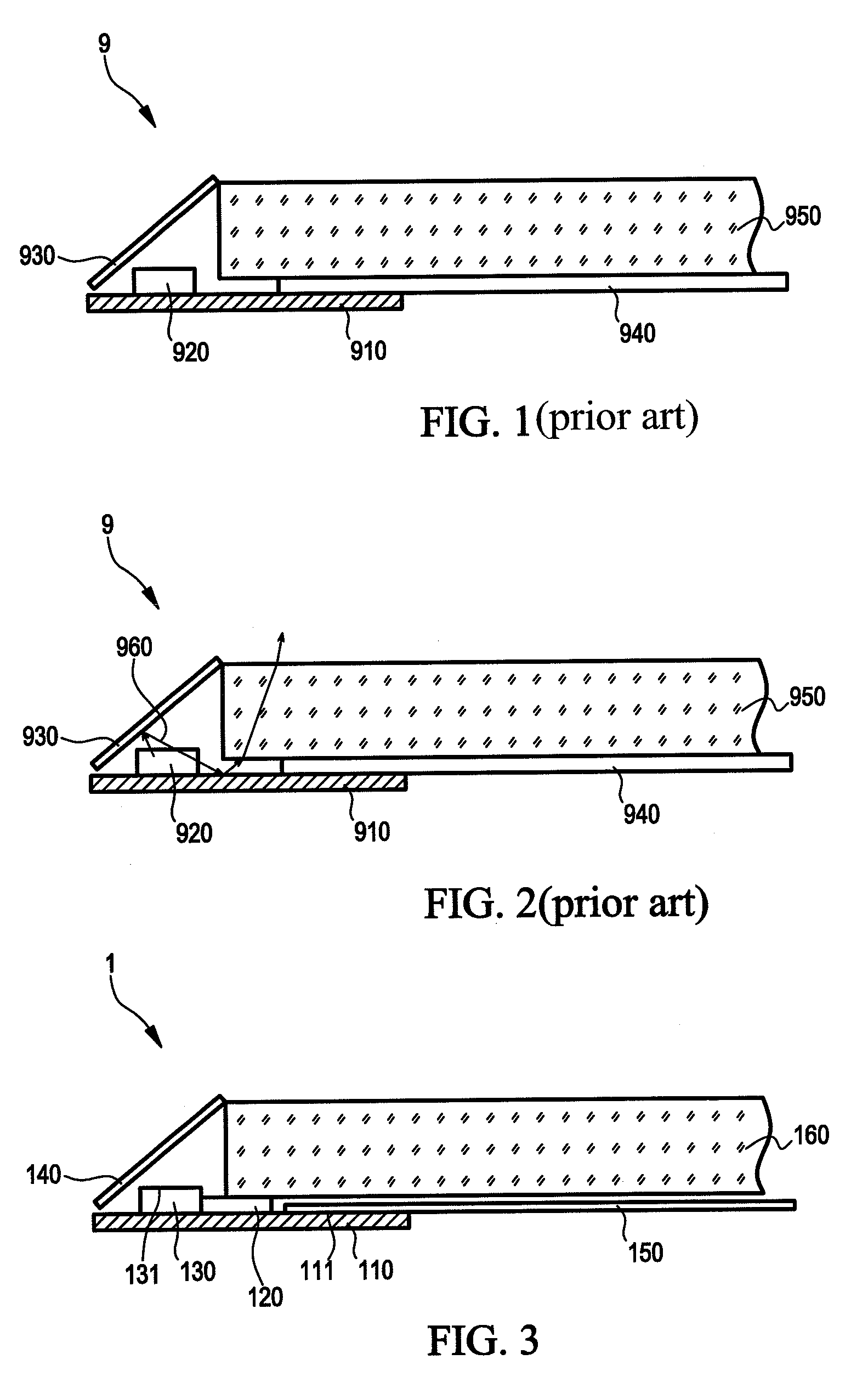
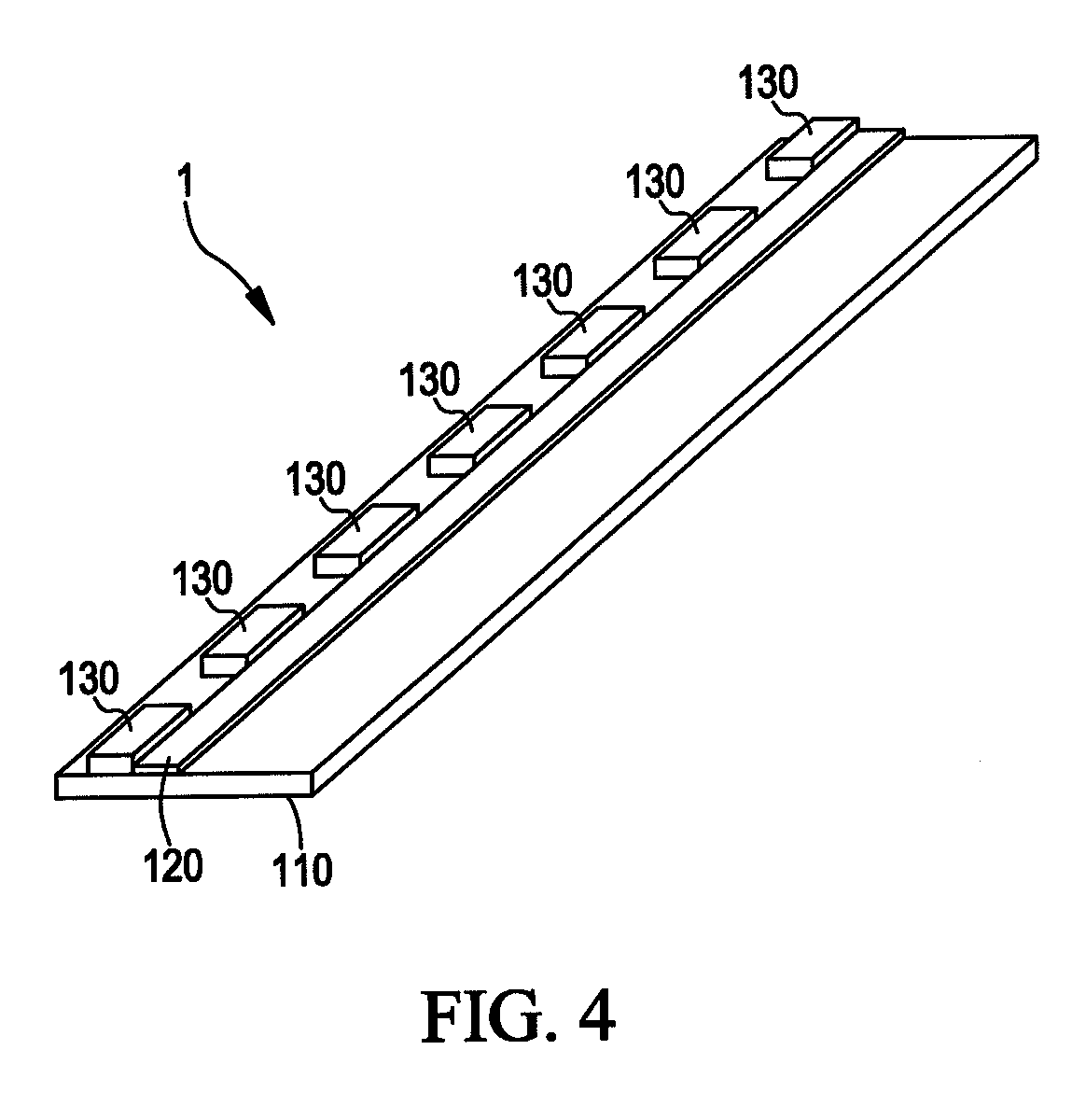
[0031]The light emitting diodes 130 are disposed on a left part of the printed circuit board 110 and the reflective film 150 is disposed on a right part of the printed circuit board 110. The absorbing surface 120 is disposed on the supporting surface 111 and between the light emitting diodes 130 and the reflective film 150. The absorbing surface 120 is disposed beside the light emitting diodes 130 for absorbing the light reflected by the reflective surface 140. The absorbing surface 120 can be extended towards the reflective film 150 so that part of the absorbing surface 120 is located between the reflective film 150 and the light guide plate 160. The light guide plate 160 is disposed above the reflective film 150 so that the reflective film 150 is located between the light guide plate 160 and the supporting surface 111. The reflective surface 140 is disposed on a side edge of the light guide plate 160 and is kept a distance from the light emitting diodes 130. The reflective surface...

fourth embodiment

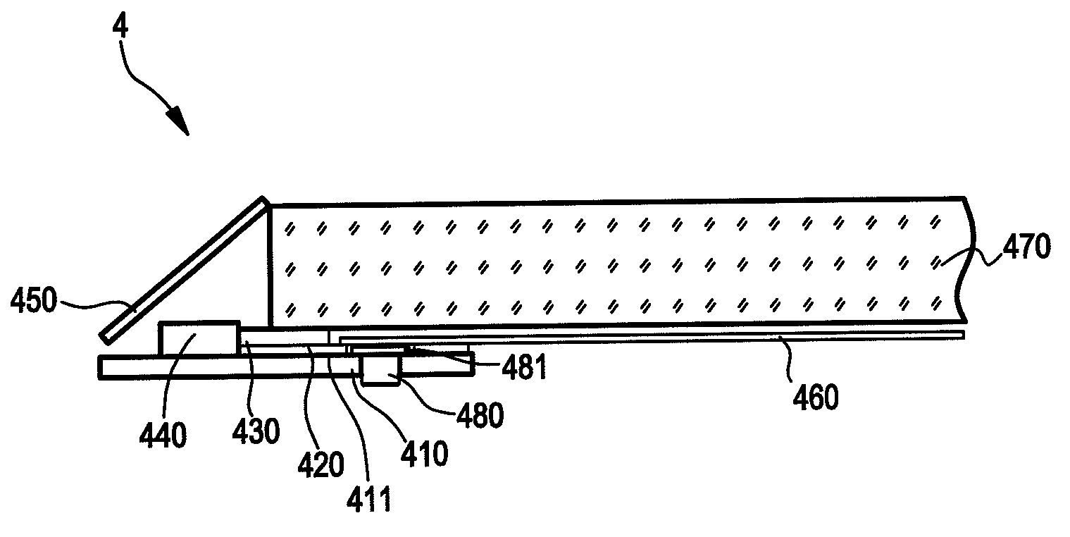
[0035]The light emitting diodes 440 are disposed on a left part of the printed circuit board 410 and the reflective film 460 is disposed on a right part of the printed circuit board 410. The first tape 420 is disposed between the supporting surface 411 and the reflective film 460 and located beside the light emitting diode 440. A width of the first tape 420 is equal to or smaller than a distance from the light emitting diode 440 to an edge of a right part of the supporting surface 411. The first tape 420 comprises a hole used to avoid touching with the screw 480 disposed between the printed circuit board 410 and the reflective film 460. The screw 480 penetrates through the first tape 420 and a right side of the printed circuit board 410. The screw 480 is disposed under the reflective film 460 for securing the printed circuit board 410. The light guide plate 470 is disposed above the reflective film 460 so that the reflective film 460 is disposed between the light guide plate 470 and...


PUM

PropertyMeasurementUnit
distanceaaaaaaaaaa
thermally conductiveaaaaaaaaaa
thicknessaaaaaaaaaa

Abstract

An edge-type backlight module and a liquid crystal display using the same. The edge-type backlight module comprising a printed circuit board having a supporting surface; plural light emitting diodes disposed on the supporting surface, each of the light emitting diodes comprising a light emitting surface and the light emitted by the light emitting diode being emitted from the light emitting surface; a reflective film disposed on the supporting surface; a light guide plate disposed above the reflective film so that the reflective film being disposed between the light guide plate and the supporting surface; a reflective surface disposed on a side edge of the light guide plate and kept a distance from the light emitting diode, the reflective surface used for reflecting the light emitted from the light emitting surface; and a dark surface disposed on the supporting surface for absorbing the light reflected by the reflective surface.

Description

FIELD OF THE INVENTION[0001]The present invention relates to an edge-type backlight module and a liquid crystal display using the same, and more particularly to an edge-type backlight module having a dark surface and a liquid crystal display using the same.BACKGROUND OF THE INVENTION[0002]The backlight module is a critical component for liquid crystal display (LCD) panels because the liquid crystal does not emit light itself. A backlight module is mainly used for providing a light source with enough brightness and evenly distributed so that an LCD panel can display images normally. As LCD panels are widely used in electronic products such as monitors, notebook computers, digital cameras and projectors, etc., the demands for backlight modules and related components are growing continuously.[0003]Generally speaking, the backlight module is divided into two types, which are the direct-type backlight module and the edge-type backlight module. In the direct-type backlight module, a backl...

Claims


Application Information

Patent Timeline
Patent Type & Authority Patents(United States)
IPC IPC(8): G02F1/1335G02F1/1333F21V7/04F21V8/00
CPCG02B6/0083G02B6/0023G02B6/0031
Inventor TANG, GUOFU
Owner TCL CHINA STAR OPTOELECTRONICS TECH CO LTD
Why Eureka
Try Eureka