
Periodic permanent magnet focused klystron

a permanent magnet and focused klystron technology, applied in the field of klystron, can solve the problems of cooling circuitry affecting the operating cost, system which requires special sitting considerations, and difficulty in design and implementation

Active Publication Date: 2015-04-21
CALABAZAS CREEK RES
View PDF9 Cites 5 Cited by
  • Summary
  • Abstract
  • Description
  • Claims
  • Application Information

AI Technical Summary

Benefits of technology

The patent describes a periodic permanent magnet klystron that has a unique design with alternating magnetic field generators. The design allows for the generation of an axial magnetic field that interacts with an electron beam to create beam transport through the klystron. The resulting klystron assembly provides improved performance and stability compared to traditional klystrons.

Problems solved by technology

The resulting overall size and power consumption of the main axial field components results in a system which requires special siting considerations.
For large accelerator systems, elimination of the solenoid and the associated power supply and cooling circuitry also impacts the operating cost.
However, the klystron also has specific requirements that cause difficulty in design and implementation.
Whereas a TWT tends to have an electron velocity at the final RF output which varies only slightly from maximum to minimum velocity, the final electron velocity in the output cavity of a klystron has a much greater variance, including the possibility that the electron velocity in the klystron may approach 0, which can cause retrograde electron movement, causing an associated degradation in efficiency.

Method used


Image

  • Periodic permanent magnet focused klystron
  • Periodic permanent magnet focused klystron
  • Periodic permanent magnet focused klystron

Examples


Embodiment Construction

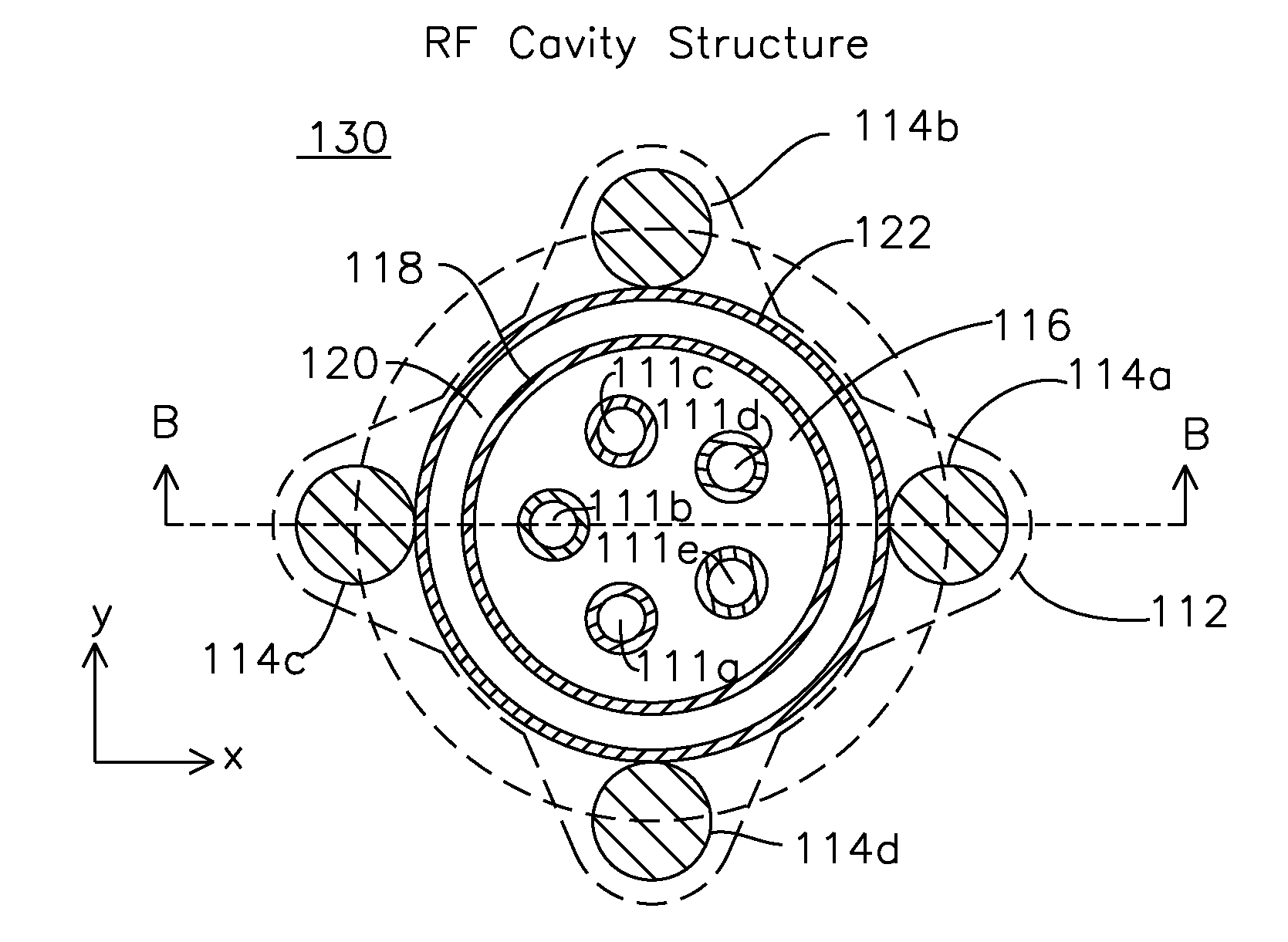
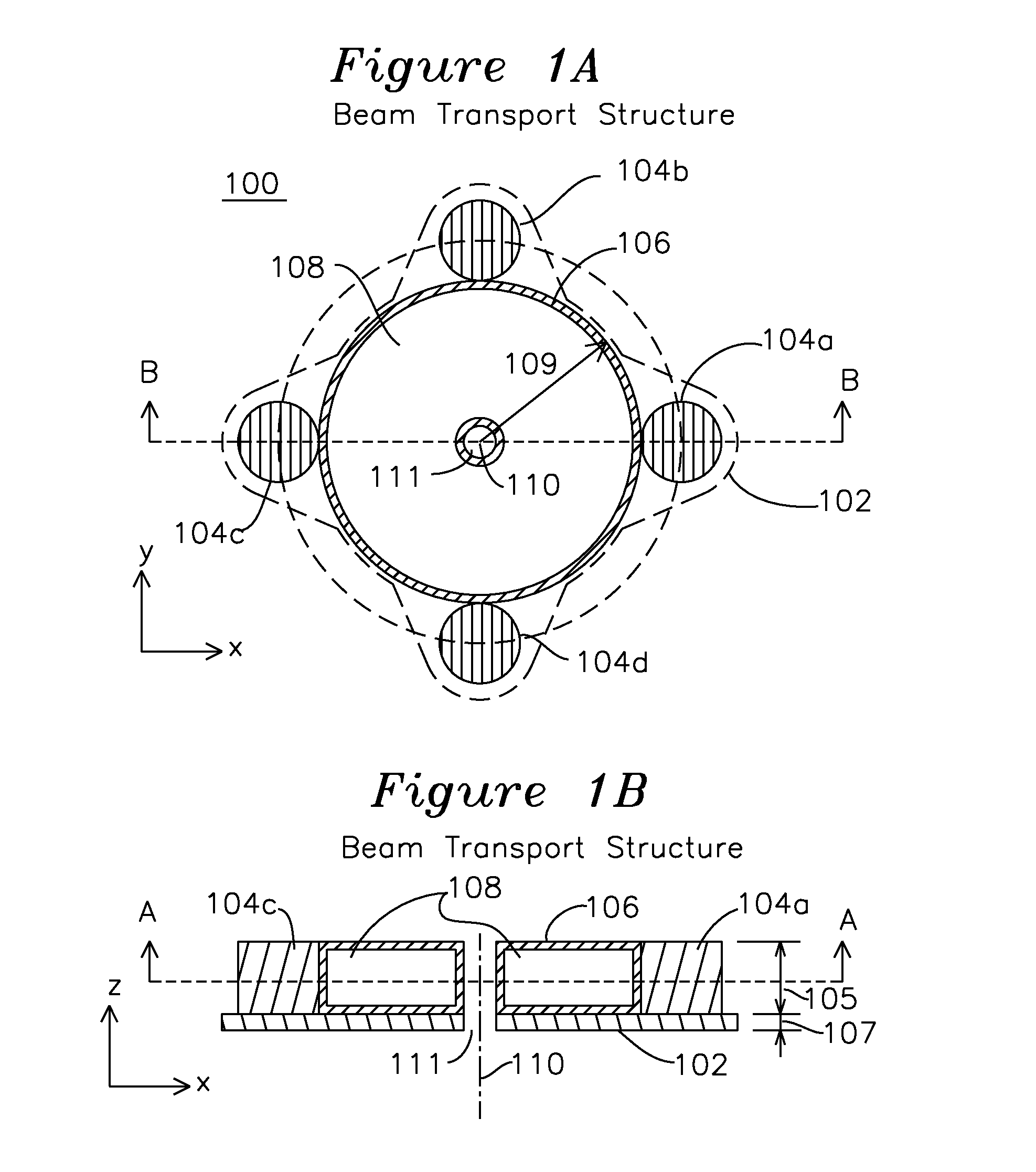
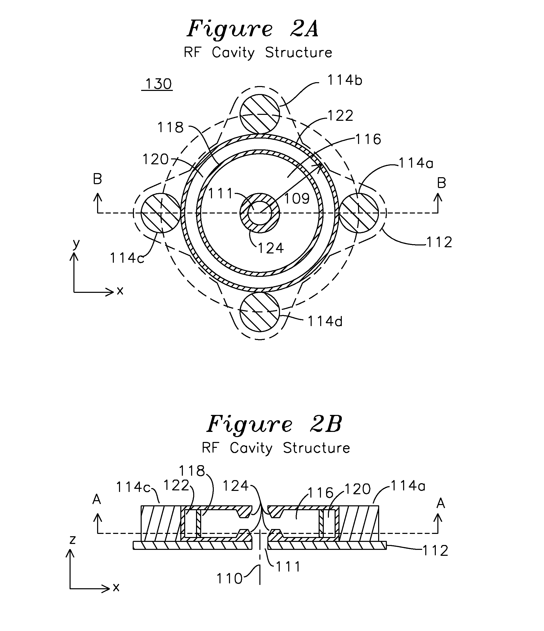
[0032]FIGS. 1A and 1B show a beam transport structure 100. FIG. 1A is best understood in combination with FIG. 1B showing section B-B of FIG. 1A, which shows a projected section view A-A of FIG. 1B. The beam transport structure comprises a ferrous pole piece 102 which is adjacent to substantially cylindrical permanent magnets 104a, 104b, 104c, 104d positioned in a uniform radial extent about the central z axis 110 and beyond a radial distance 109 from the central axis 110 where a beam tunnel 111 is formed by the inner radius of enclosed coolant chamber 108, which is coupled to liquid coolant (not shown) for circulation to remove heat from the beam transport structure 100. Typically, the cylindrical permanent magnets 104a, 104b, 104c, 104d are of identical construction and are positioned a uniform radial distance from the center axis 110 to create a uniform z-axis magnetic field, which reverses polarity with each subsequent structure, as will be described. Cylindrical permanent magne...


PUM


Abstract

A periodic permanent magnet (PPM) klystron has beam transport structures and RF cavity structures, each of which has permanent magnets placed substantially equidistant from a beam tunnel formed about the central axis, and which are also outside the extent of a cooling chamber. The RF cavity sections also have permanent magnets which are placed substantially equidistant from the beam tunnel, but which include an RF cavity coupling to the beam tunnel for enhancement of RF carried by an electron beam in the beam tunnel.

Description

[0001]The present invention claims priority to provisional patent application 61 / 814,401 filed Apr. 22, 2013.[0002]The present invention was developed under the U.S. Department of Energy grant No. DE-SC0004558. The government has certain rights in this invention.FIELD OF THE INVENTION[0003]The present invention relates to a klystron. In particular, the invention relates to a klystron which uses periodic permanent magnets for beam focusing, with the permanent magnets generating an axial magnetic field which reverses polarity along an axial extent of a beam tunnel.BACKGROUND OF THE INVENTION[0004]Current medical imaging systems use a klystron to develop X-rays for medical therapeutic use by impinging a high speed electron beam onto a target which generates x-rays, and the x-rays are used for treatment of cancerous tumors. In a clinical use linear accelerator (such as the CLINAC® system manufactured by Varian medical systems), a klystron, linear accelerator, and x-ray target are mounte...

Claims


Application Information

Patent Timeline
Patent Type & Authority Patents(United States)
IPC IPC(8): H01J23/08H01J23/087H01J25/10
CPCH01J25/10H01J23/0873
Inventor FERGUSON, PATRICKREAD, MICHAELIVES, R. LAWRENCE
Owner CALABAZAS CREEK RES
Learn More