
Apparatus and method for use in the treatment of hammertoe

a technology of hammertoe and apparatus, applied in the field of orthopaedics, can solve the problems of affecting the healing effect of patients with digital deformities. , to achieve the effect of promoting bone regeneration, strong and durable connection, and speeding up healing

Inactive Publication Date: 2015-04-21
NSPIRED IDEAS +2
View PDF6 Cites 18 Cited by
  • Summary
  • Abstract
  • Description
  • Claims
  • Application Information

AI Technical Summary

Benefits of technology

The current device has various components that work together to create an efficient and secure connection between the device and the host material or bone. The device uses interlocking hook threads that provide sharp cutting edges and a strong connection with the host material. The device also has an adjustable drawing capability that allows for secure bone pinning. The interlocking hook threads help promote bone regeneration and faster healing. The device is easy to assemble, load-bearing, and can be reused if needed. Overall, the device helps to accelerate bone healing and recovery after surgery.

Problems solved by technology

Patients with digital deformities often experience significant pain from structural abnormalities.
Although this type of surgical procedure has alleviated the discomfort of hammer toe and other abnormalities of the toe and finger joints for countless patients, the use of K-wire can result in the possible post-surgical misalignment of the phalanges (e.g., caused by distraction of the K-wire), as well as swelling, inflammation, and possible infection at the site of the exposed K-wire segment.
These devices are typically comprised of metallic or thermoplastic materials which, while being biocompatible, are also physiologically inert and thus are not resorbed by the body.
There are, however, conditions in which an arthrodesis, or fusing of the affected finger or toe joint is desired, making a permanent device which is designed to permit joint flexion / extension inappropriate.

Method used


Image

  • Apparatus and method for use in the treatment of hammertoe
  • Apparatus and method for use in the treatment of hammertoe
  • Apparatus and method for use in the treatment of hammertoe

Examples


Embodiment Construction

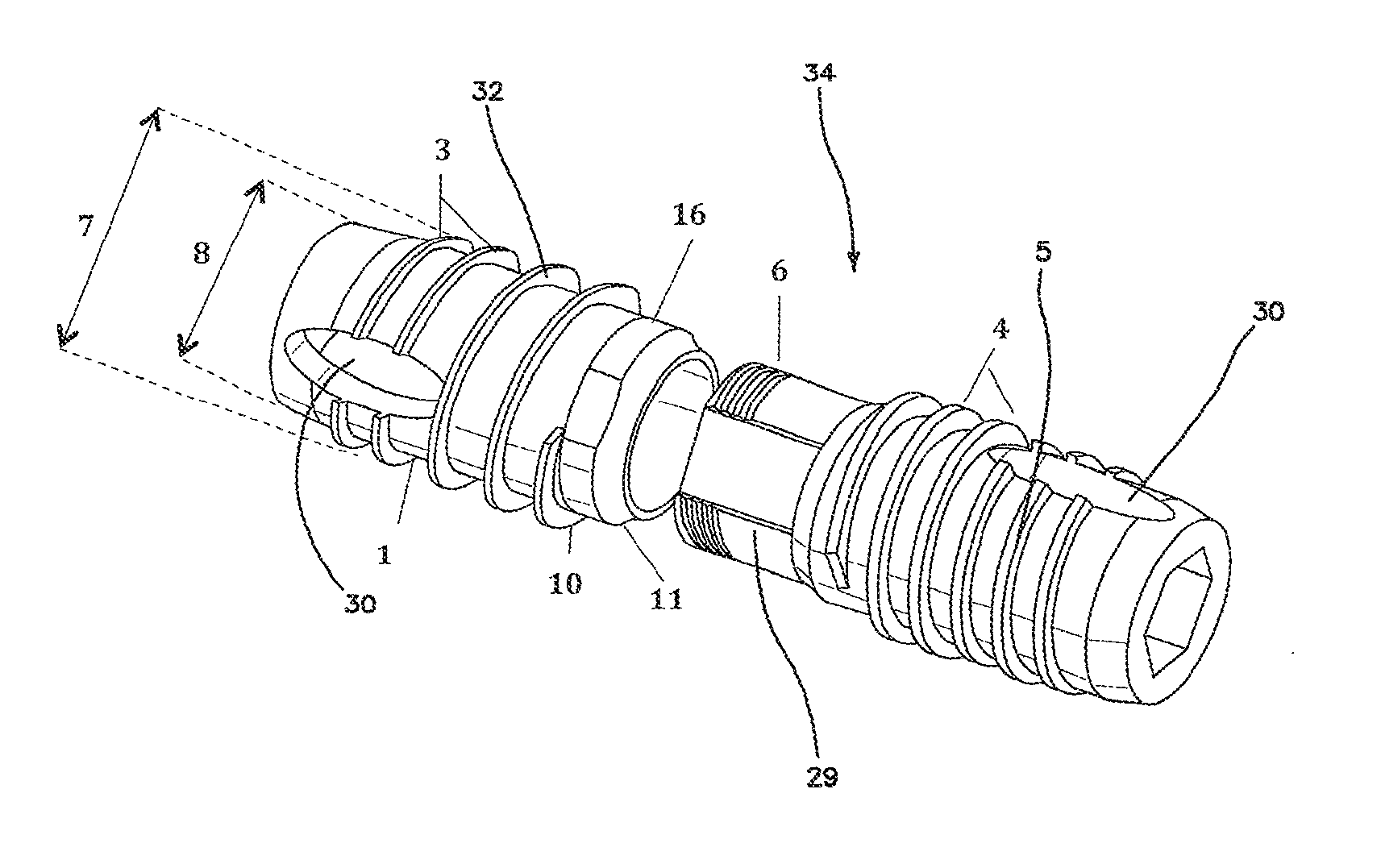
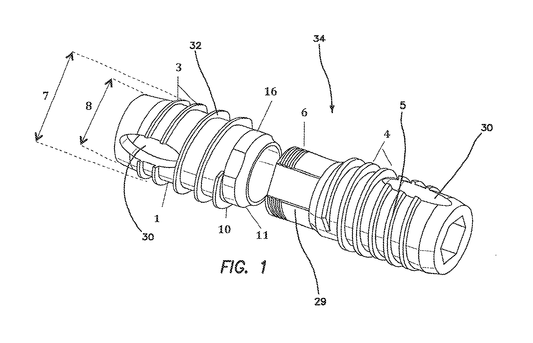
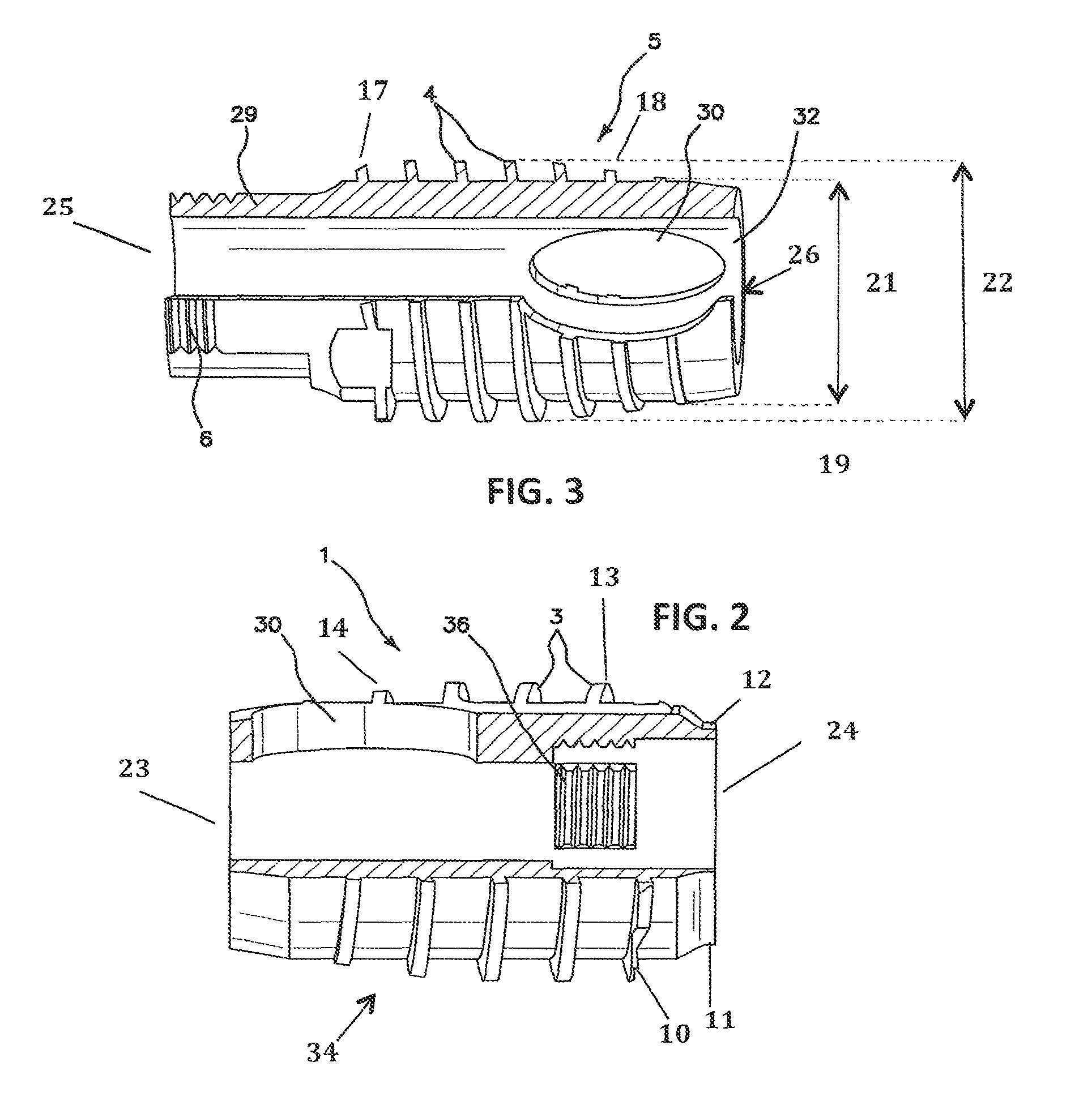
[0046]Turning now to FIG. 1, a distal half 1 and a proximal half 5 of the bone pin 34 are shown. As described below distal half 1 is implanted in the distal phlange and proximal half 5 is implanted into the proximal phlange of a hammer toe joint. Both halves 1, 5 are generally cylindrical with a longitudinal bore define therethrough on the longitudinal axis of each half. The distal half 1 includes an external helical thread 3 defined into the exterior surface of the distal half 1. The tooth 32 of the external helical thread 3 is defined between a minor diameter 8 and a major diameter 7. Similarly, an external helical thread 4 is also defined into the exterior surface of the proximal half 5, however the external thread 3 of the distal half 1 has a greater pitch than that of the threads 4 of the proximal half 5. The proximal half 5 further comprises a male peg 29 on its distal end. An external helical thread 6 is defined into the exterior surface of the male peg 29. A mating internal ...


PUM


Abstract

The apparatus and method is directed to a pair of self-tapping, interconnecting, externally and internally threaded devices that, when installed between two separate pieces of material, will draw and hold the material together as a single threaded unit. While the pair of threaded devices are being fastened into the host material, due to the unique design of their threads, no radial outward forces are produced that could cause cracking or splitting of the sections of the material into which they are installed. The external threads are helically defined into the exterior of each half of the device with a right hand thread defined into one half and a left hand thread into the other half. When the two halves are being fastened together, the increased thread pitch on one of the halves continuously draws the halves into each other even when the internal threads have already been maximally tightened.

Description

BACKGROUND OF THE INVENTION[0001]1. Field of the Invention[0002]The invention relates to the field of orthopedics, and more particularly to a bone pin for the coupling of two separate pieces of bone together for use in the surgical correction of hammer toe.[0003]2. Description of the Prior Art[0004]One surgical method of treatment of hammertoe involves the surgical implantation of bone pins, and more particularly, an interphalangeal fusion pin which provides an anatomically correct angle between a first phalange and a second phalange, such as the proximal phalange and the intermediate phalange which exists at the proximal interphalangeal joint, wherein the pin is comprised of a resorbable or permanent material.[0005]Digital deformities of the fingers and toes are some of the most common conditions encountered by orthopedists and podiatrists. Patients with digital deformities often experience significant pain from structural abnormalities. Some of these abnormalities are acquired, ca...

Claims


Application Information

Patent Timeline
Patent Type & Authority Patents(United States)
IPC IPC(8): A61B17/86A61B17/72A61F2/30A61F2/42
CPCA61B17/8685A61B17/7225A61B17/7291A61F2/4225A61F2002/30235A61F2002/30622A61F2002/30772A61F2002/3085A61F2002/423A61F2230/0069A61F2002/4228A61F2220/0008
Inventor REED, GARY
Owner NSPIRED IDEAS
Learn More