
System and methods for dynamic erase and program control for flash memory device memories

Active Publication Date: 2015-03-31
AVAGO TECH INT SALES PTE LTD
View PDF331 Cites 44 Cited by
  • Summary
  • Abstract
  • Description
  • Claims
  • Application Information

AI Technical Summary

Benefits of technology

[0135]The flash memory controller may be arranged to find a set of erase parameters tha

Problems solved by technology

Those are the mechanisms that may cause reliability failure.
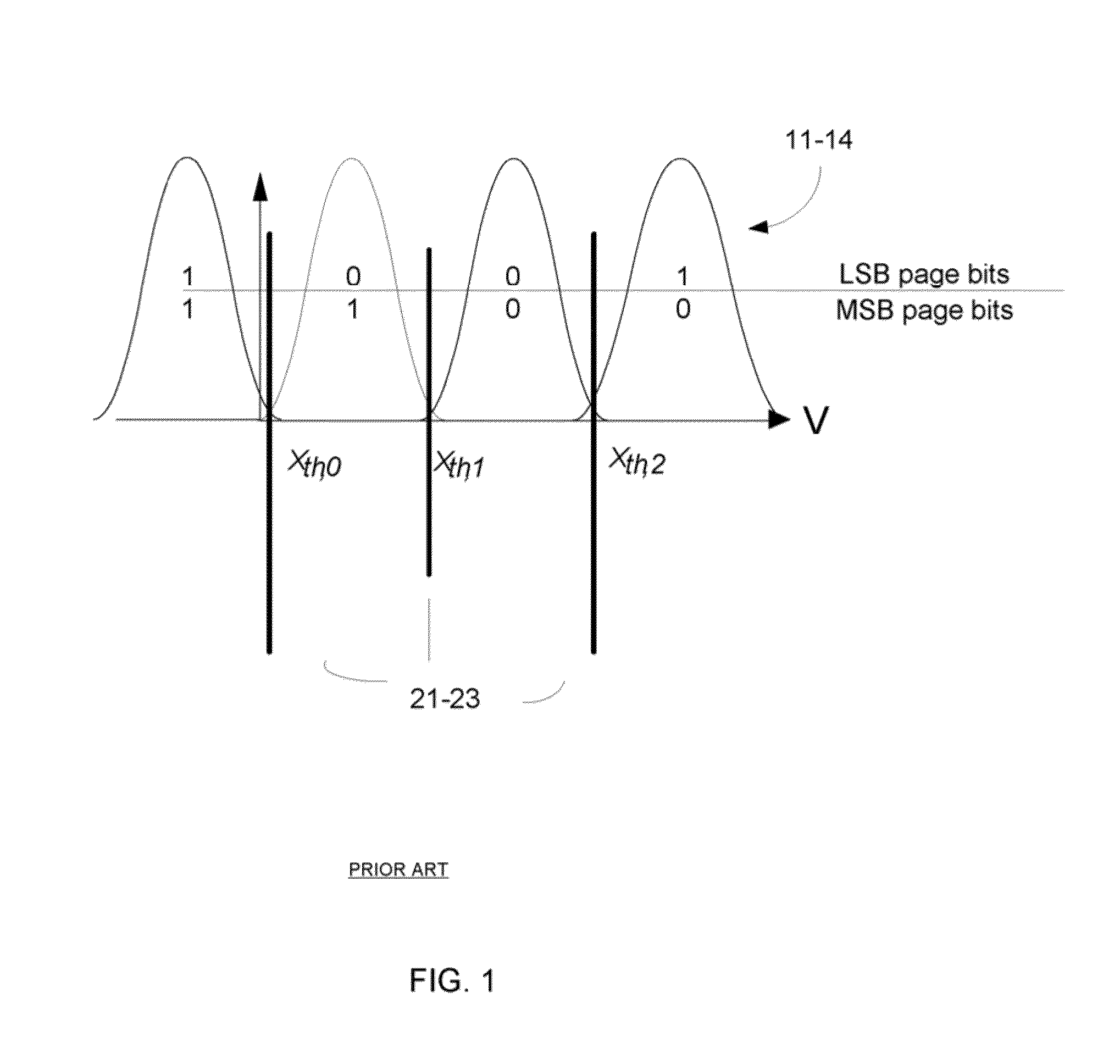
The voltage programming and readout are statistical, and there is therefore a probability of error in each decision.
These techniques, however, require a high electric field in the oxide and may create traps and leakage current.
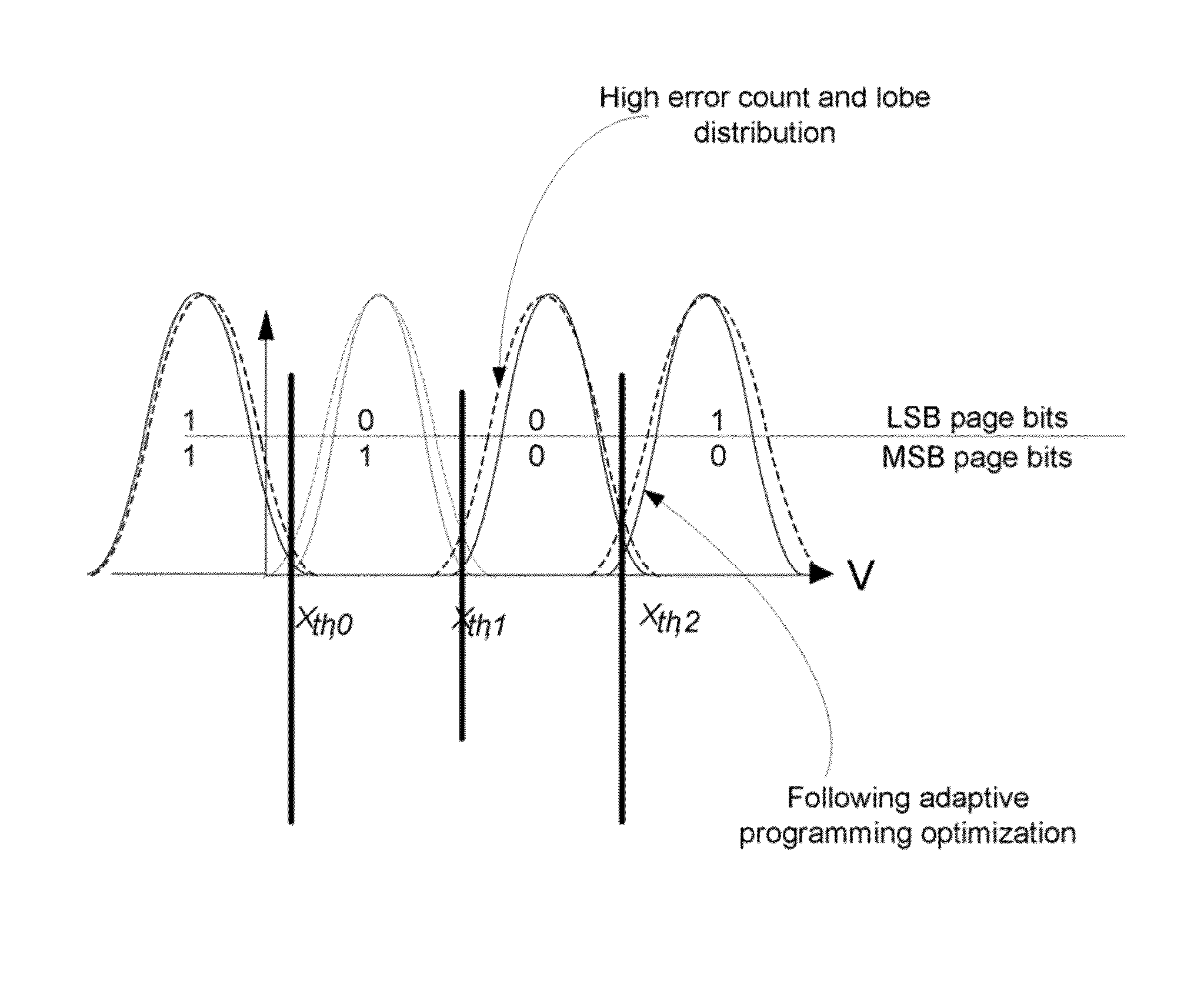
The result of performing program and erase (P/E) cycles with a fixed set of flash memory device parameters may be highly inefficient.
However, it also increases the threshold variance for every level in the program.
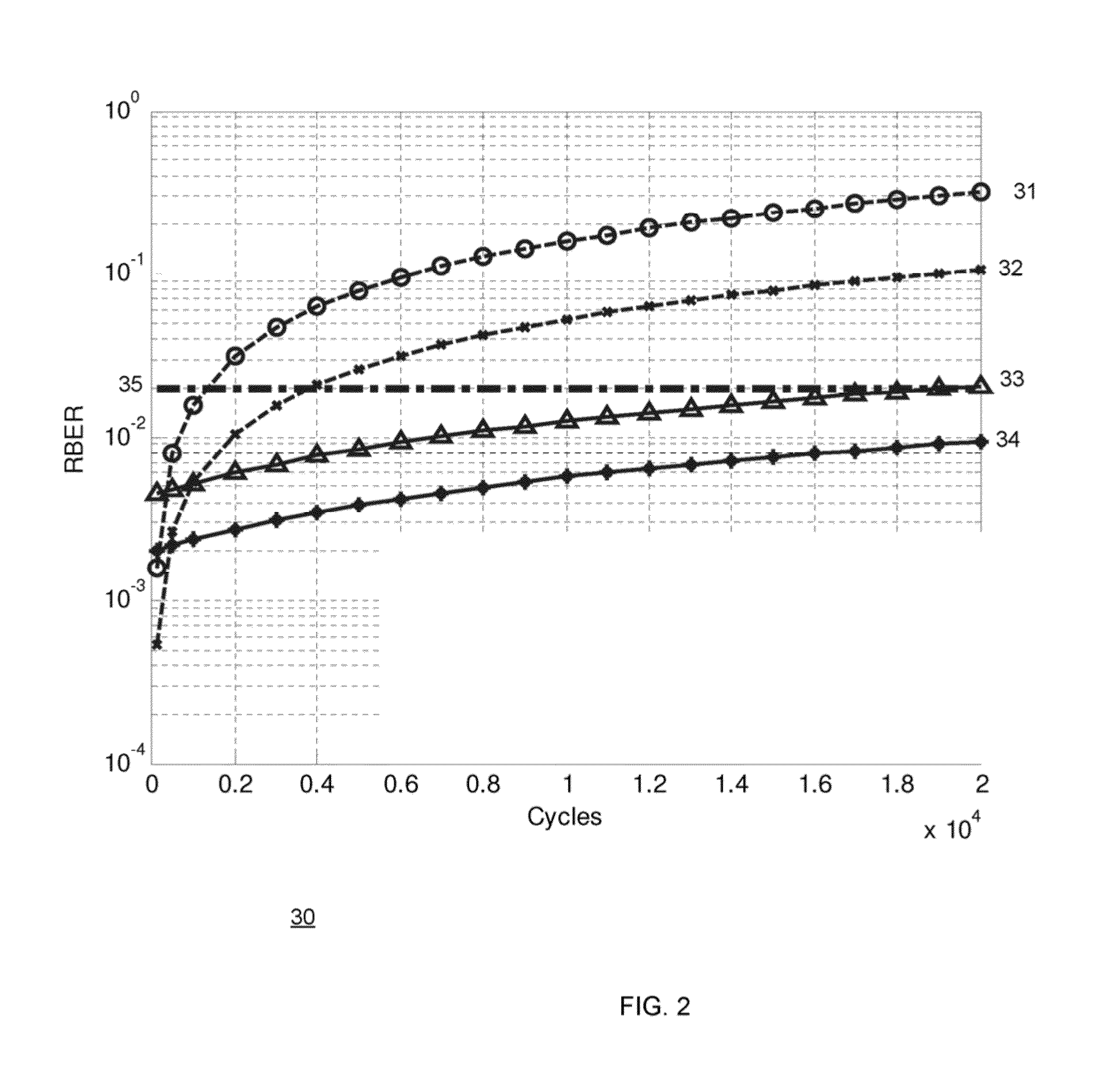
The device bit error rate (BER) may therefore not be constant with respect to the cycle count and the numbers of errors may constantly increase as the number of cycle increases.
The method may include finding a set of evaluated parameters that once applied results in manageable level of bit error rates that exceeds a minimal allowable level of bit error rates.
The method may include selecting a set of evaluated parameters that once applied results in manageable level of bit error rates and has a smallest contribution to a wear level of the at least one group of flash memory cells.
The method may include selecting a set of evaluated parameters that once applied results in a higher bit error rate at low wear levels and a lower increment rate of bit error rates per wear level in relation to at least one other set of evaluated parameters.
The method may include selecting a set of evaluated parameters that once applied results in a higher bit error rate at low wear levels and at a lower increment rate of bit error rates per wear level in relation to a reference set of parameters that is expected to be applied regardless of a wear level of the at least one group of flash memory cells.
The method may include repetitively programming the same information to multiple groups of flash memory cells is a probability of a programming operation failure exceeds a threshold.
Sub-ranges of higher order may be associated with higher wear levels.
The non-transitory computer readable medium may store instructions for finding a set of evaluated parameters that once applied results

Method used


Image

  • System and methods for dynamic erase and program control for flash memory device memories
  • System and methods for dynamic erase and program control for flash memory device memories
  • System and methods for dynamic erase and program control for flash memory device memories

Examples


Example

[0142]It will be appreciated that for simplicity and clarity of illustration, elements shown in the figures have not necessarily been drawn to scale. For example, the dimensions of some of the elements may be exaggerated relative to other elements for clarity. Further, where considered appropriate, reference numerals may be repeated among the figures to indicate corresponding or analogous elements.

DETAILED DESCRIPTION OF THE DRAWINGS

[0143]In the following detailed description, numerous specific details may be set forth in order to provide a thorough understanding of the invention. However, it will be understood by those skilled in the art that the present invention may be practiced without these specific details. In other instances, well-known methods, procedures, and components have not been described in detail so as not to obscure the present invention.

[0144]The subject matter regarded as the invention is particularly pointed out and distinctly claimed in the concluding portion of...


PUM


Abstract

A computer readable medium, a system and a method for flash memory device parameter optimization, the method may include: receiving or generating an estimate of a wear level of at least one group of flash memory cells of the flash memory device, and finding erase parameters and programming parameters to be applied on one or more groups of flash memory cells of the flash memory device in response to estimate of the wear level.

Description

RELATED APPLICATIONS[0001]This application is a continuation in part of U.S. patent application Ser. No. 12 / 769,208 having a filing date Apr. 28, 2010, which is incorporated herein by reference.BACKGROUND OF THE INVENTION[0002]Flash memory device cells are used widely in the industry as memory storage. The flash memory device cell must be able to program, erase and retain charge on its floating gate. During program or erase the flash memory device cell is subject to high electric field to support oxide tunneling and hot electron injection. Those are the mechanisms that may cause reliability failure. Most of the available digital integrated circuits (IC) operate on rail-to-rail logic, flash memory device operation is distinctively analog. The digitally stored information induces analog distribution of the threshold voltage for read operations. In multi-level flash memory device cells, multiple bits are stored by precise placement of threshold voltage in each cell. The readout of the ...

Claims


Application Information

Patent Timeline
IPC IPC(8): G11C11/34G06F12/02
CPCG06F12/0246G06F11/1048G11C11/5628G11C16/04G11C16/10G11C16/349G11C29/00G11C29/028G11C29/52G11C2029/0409G11C2211/5644G11C11/5635G11C16/14G11C16/3495G11C29/021G11C2029/0411
Inventor STEINER, AVIWEINGARTEN, HANAN
Owner AVAGO TECH INT SALES PTE LTD
Learn More