
Sintered gearwheel

a gearwheel and gear wheel technology, applied in the field of gearwheels, can solve the problems of high deformation, material defects, material flaking and lapping, etc., and achieve the effect of increasing the load-bearing capacity

Inactive Publication Date: 2015-03-24
MIBA SINTER AUSTRIA
View PDF17 Cites 3 Cited by
  • Summary
  • Abstract
  • Description
  • Claims
  • Application Information

AI Technical Summary

Benefits of technology

[0005]The invention is therefore based on the object of providing a sintered gearwheel of the kind mentioned above in such a way that its load-bearing capacity can be increased considerably.
[0007]Powder metal blanks are sintered with an oversize corresponding to the surface layer to be compacted for the production of sintered gearwheels with teeth which have a compacted surface layer in the flank and root region. They are calibrated to the nominal size under compaction of the surface layer in the region of the oversize by means of a pressing tool which forms a counter-toothing. During the rolling engagement of the counter-toothing of the pressing tool into the toothing of the sintered powder metal blank, a penetration of the tips of the teeth of the counter-toothing of the pressing tool into the sintered powder metal blank will occur predominantly in the transitional portion between the flank and root region of the teeth, leading to a very high degree of deformation which may lead to material defects such as flaking and lapping of the material. As a result of a reduction in the thickness of the oversize of the sintered powder metal blank in the transitional region between the flank and root region of the teeth, the degree of deformation caused by processing with the pressing tool can be reduced to a level which does not lead to any flaking or lapping of the material which might impair the load-bearing capacity of the compacted material. For this reason, a reduced thickness of the compacted surface layer in the transitional region between the flank and the root region leads to a considerable increase in the load-bearing capacity of the sintered gearwheel in combination with good root-strength of the teeth.

Problems solved by technology

During the rolling engagement of the counter-toothing of the pressing tool into the toothing of the sintered powder metal blank, a penetration of the tips of the teeth of the counter-toothing of the pressing tool into the sintered powder metal blank will occur predominantly in the transitional portion between the flank and root region of the teeth, leading to a very high degree of deformation which may lead to material defects such as flaking and lapping of the material.

Method used


Image

  • Sintered gearwheel
  • Sintered gearwheel

Examples


Embodiment Construction

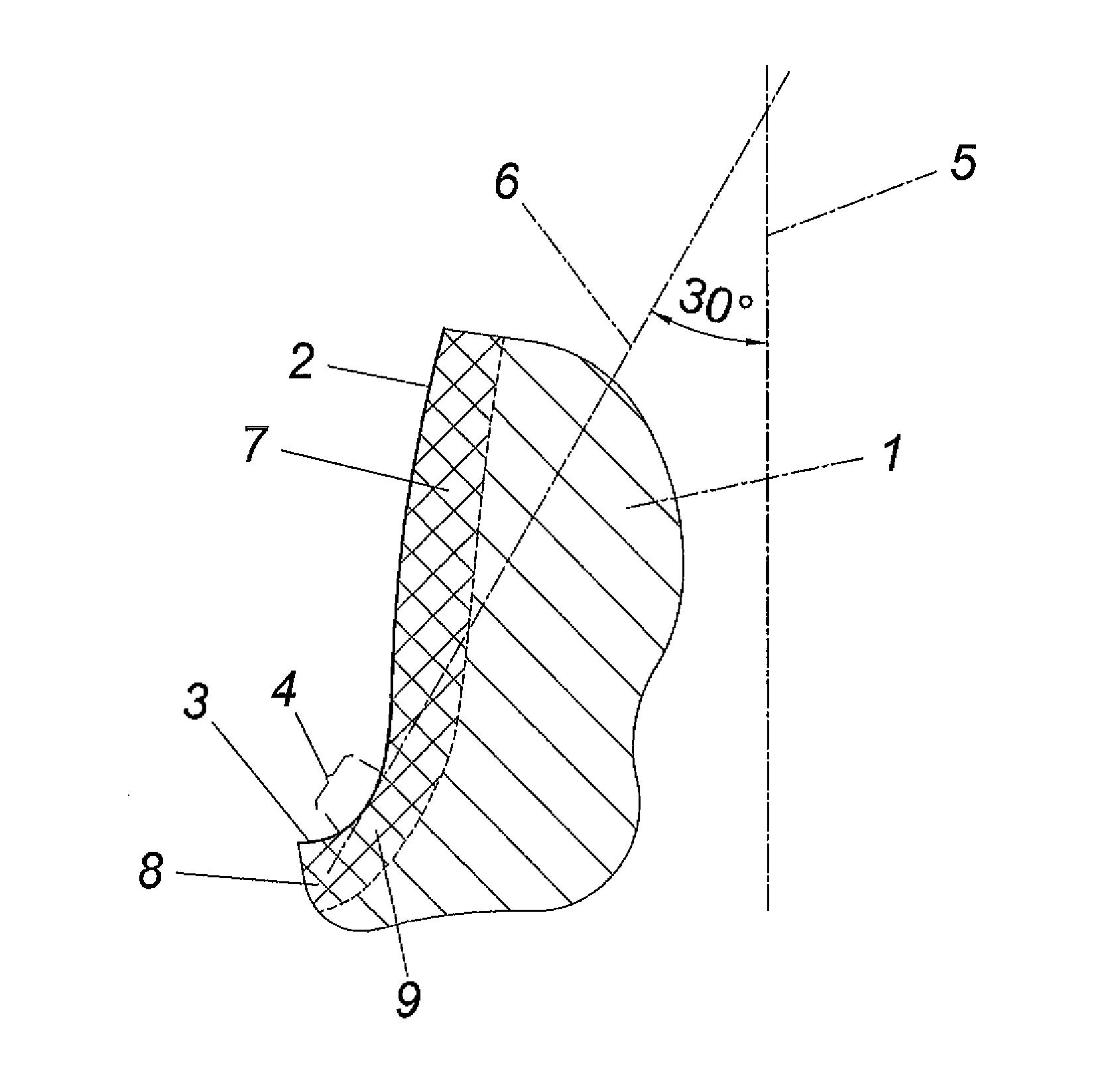
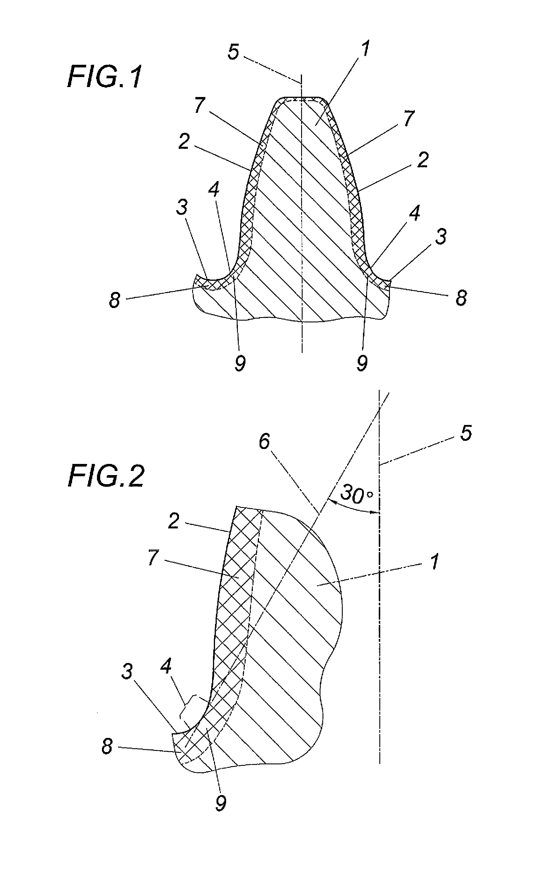
[0012]The tooth 1 of a sintered gearwheel (not shown in closer detail) forms a tooth flank region 2 and a root region 3 in a conventional manner. The transitional portion between these two regions 2 and 3 is designated with reference numeral 4 and is generally determined by tangent 6 on the contour of tooth 1, which tangent 5 is inclined under 30° in relation to the tooth axis 5, as is shown in FIG. 2.

[0013]A compacted surface layer is provided in the flank and root region 2, 3 of the tooth 1, which compacted surface layer is designated in the tooth flank region with reference numeral 7 and in the tooth root region with reference numeral 8, with a surface layer 9 being obtained in the transitional region 4 which converges continually into the surface layers 7, 8. Said compacted surface layers 7, 8 and 9 have a residual porosity of less than 10% which decreases towards the surface of the tooth, so that a substantially dense material can be expected in the direct surface region. The c...


PUM

PropertyMeasurementUnit
residual porosityaaaaaaaaaa
thicknessaaaaaaaaaa
thicknessaaaaaaaaaa

Abstract

A sintered gearwheel is described having teeth (1) which, in the flank and root region (2, 3), comprise a compacted surface layer (7, 8, 9) which is continuous in the transition portion (4) between the flank and root region (2, 3) and has a residual porosity of less than 10%. In order to increase the load-bearing capacity it is proposed that the compacted surface layer (9) is formed with a lower thickness in the transitional portion (4) between the flank and root region (2, 3) than in the adjacent flank and root regions (2, 3).

Description

CROSS REFERENCE TO RELATED APPLICATIONS[0001]This application is the National Stage of PCT / AT2011 / 000289 filed on Jul. 1, 2011, which claims priority under 35 U.S.C. §119 of Austrian Application No. A 1454 / 2010 filed on Aug. 31, 2010, the disclosure of which is incorporated by reference. The international application under PCT article 21(2) was not published in English.FIELD OF THE INVENTION[0002]The invention relates to a sintered gearwheel having teeth which, in the flank and root region, comprise a compacted surface layer which is continuous in the transition portion between the flank and root region and has a residual porosity of less than 10%.DESCRIPTION OF THE PRIOR ART[0003]In order to achieve a higher bending endurance in the region of the tooth roots and a higher wear resistance in the region of the tooth flanks in sintered gearwheels produced by means of powder metallurgy, it is known (EP 0 552 272 B1) to densify the sintered powder metal blanks of the gearwheels in the fl...

Claims


Application Information

Patent Timeline
Patent Type & Authority Patents(United States)
IPC IPC(8): F16H55/06B21H5/02B22F3/11B22F3/16B22F5/08
CPCB22F5/08B21H5/022B22F3/1109B22F3/168F16H55/06Y10T74/19949Y10T74/19963
Inventor MUELLER, ALEXANDERROESSLER, HORSTSANDNER, CHRISTIAN
Owner MIBA SINTER AUSTRIA
Learn More