
Multimode optical fiber systems with adjustable chromatic modal dispersion compensation

Active Publication Date: 2015-03-10
CORNING INC
View PDF6 Cites 3 Cited by
  • Summary
  • Abstract
  • Description
  • Claims
  • Application Information

AI Technical Summary

Benefits of technology

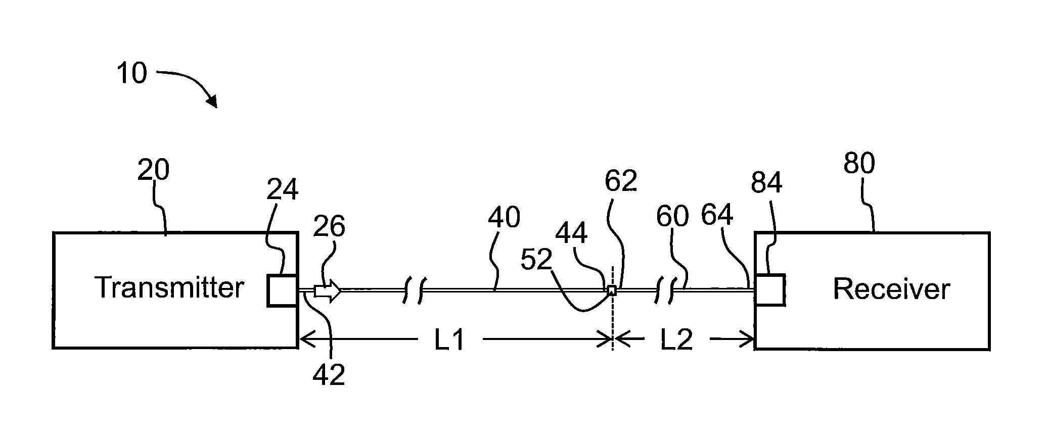
This patent describes a system and method for using a special fiber optic cable with a light source that emits different light wavelengths. The system includes a primary fiber and a compensating fiber, which work together to minimize the dispersion of light modes. The compensating fiber has a different refractive index profile and alpha value that ensures the opposite of what the primary fiber does, which helps to at least partially cancel out the dispersion. The system also includes a specific length of the compensating fiber to further enhance the performance. The technical effects of this system and method are improved bandwidth and reduced signal distortion, which result from the optimized use of the special fiber optic cable and the compensating fiber.

Problems solved by technology

This situation becomes complicated when the light source used to send light down the multimode fiber is not strictly monochromatic.
Accordingly, a multimode fiber that is optimized to have a maximum bandwidth for a given wavelength will not exhibit optimum bandwidth performance when the light source causes the different modes to have different wavelengths.
This approach is inefficient, and from a commercial telecommunications viewpoint is impractical and expensive to implement.

Method used


Image

  • Multimode optical fiber systems with adjustable chromatic modal dispersion compensation
  • Multimode optical fiber systems with adjustable chromatic modal dispersion compensation
  • Multimode optical fiber systems with adjustable chromatic modal dispersion compensation

Examples


Embodiment Construction

[0029]The symbol μm and the word “micron” are used interchangeably herein.

[0030]The term “relative refractive index,” as used herein, is defined as:

Δ(r)=[n(r)2−nREF2)] / 2n(r)2,

where n(r) is the refractive index at radius r, unless otherwise specified. The relative refractive index is defined at the fiber's peak wavelength λP. In one aspect, the reference index nREF is silica glass. In another aspect, nREF is the maximum refractive index of the cladding. As used herein, the relative refractive index is represented by Δ and its values are given in units of “%,” unless otherwise specified. In cases where the refractive index of a region is less than the reference index nREF, the relative refractive index is negative and is referred to as having a depressed region or depressed index, and the minimum relative refractive index is calculated at the point at which the relative index is most negative, unless otherwise specified. In cases where the refractive index of a region is greater than ...


PUM


Abstract

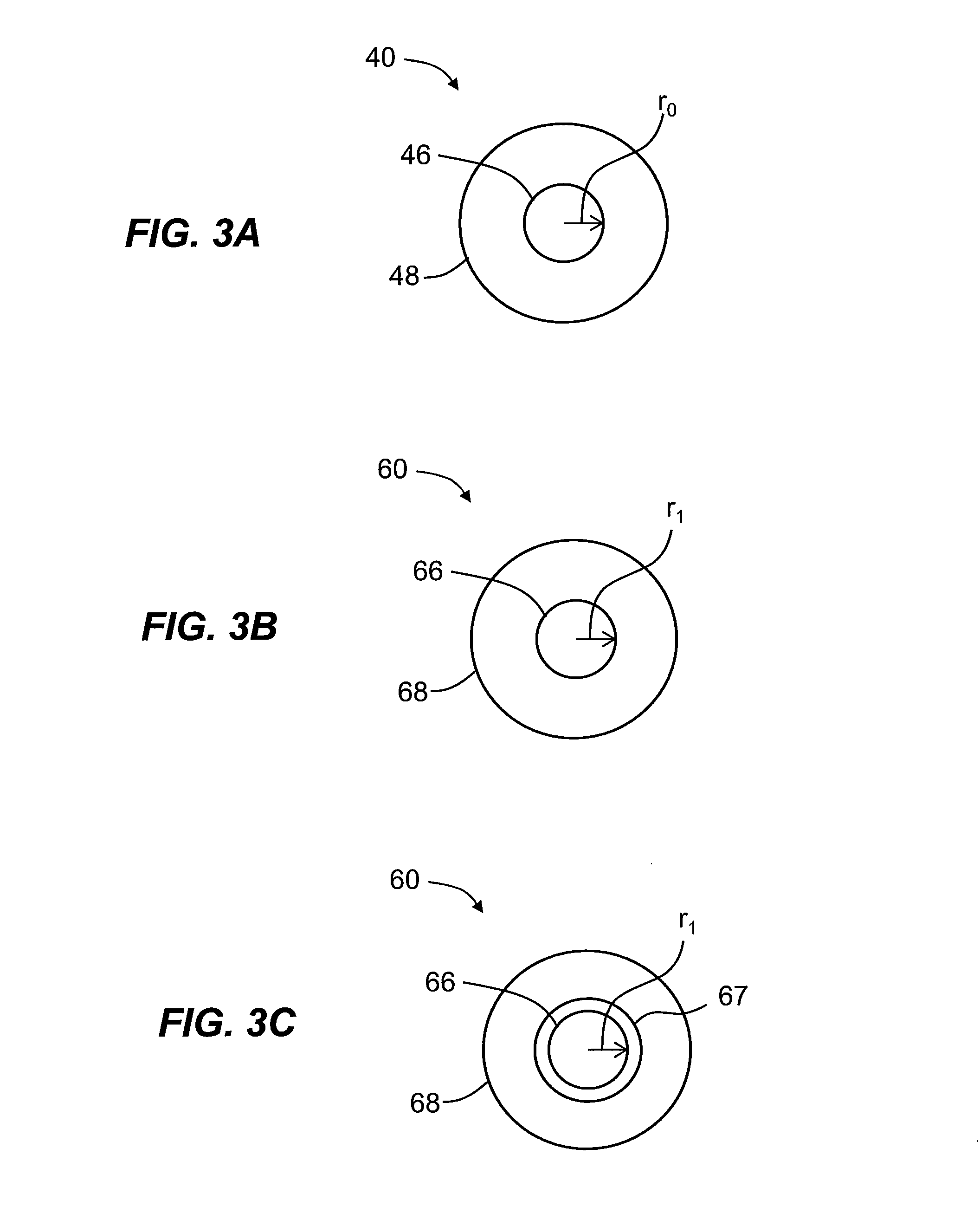
Multimode optical fiber systems with adjustable chromatic modal dispersion compensation are disclosed, wherein the system includes a VCSEL light source and primary and secondary optically coupled multimode optical fibers. Because the VCSEL light source has a wavelength spectrum that radially varies, its use with the primary multimode optical fiber creates chromatic modal dispersion that reduces bandwidth. The compensating multimode optical fiber is designed to have a difference in alpha parameter relative to the primary multimode optical fiber of −0.1≦Δα≦−0.9. This serves to create a modal delay opposite to the chromatic modal dispersion. The compensation is achieved by using a select length of the compensating multimode optical fiber optically coupled to an output end of the primary multimode optical fiber. The compensating multimode optical fiber can be configured to be bend insensitive.

Description

CROSS REFERENCE TO RELATED APPLICATIONS[0001]This application claims the benefit of priority under 35 U.S.C. §119 of U.S. Provisional Application Ser. No. 61 / 670,865 filed on Jul. 12, 2012, the content of which is relied upon and incorporated herein by reference in its entirety.FIELD[0002]The present specification relates generally to optical fibers and more specifically to multimode optical fiber systems that provide for adjustable chromatic modal dispersion compensation.[0003]All references cited herein are incorporated by reference herein.BACKGROUND[0004]Optical fibers are currently used to transmit optical signals. Optical fibers, including multimode optical fibers, are frequently used for data transmission or high-speed data transmission over distances ranging from a meter or less up to the distance needed to transmit throughout a building or between buildings near one another that are optical signals associated with local networks.[0005]Multimode fibers, by definition, are des...

Claims


Application Information

Patent Timeline
IPC IPC(8): G02B6/02G02B6/26G02B6/293
CPCG02B6/268G02B6/29376G02B6/29392G02B6/02214G02B6/0288G02B6/0365
Inventor CHEN, XINLI, MING-JUNPOWERS, DALE ROBERTVODHANEL, RICHARD STEPHEN
Owner CORNING INC
Learn More