
Melters for glass forming apparatuses

a technology of glass forming apparatus and glass forming wire, which is applied in the direction of manufacturing tools, lighting and heating equipment, furniture, etc., can solve the problems of glass ribbons that are extraordinarily thin, glass sheets and glass ribbons that are difficult to clean

Active Publication Date: 2015-03-10
CORNING INC
View PDF13 Cites 1 Cited by
  • Summary
  • Abstract
  • Description
  • Claims
  • Application Information

AI Technical Summary

Benefits of technology

The patent describes melters for melting glass batch materials that can withstand dynamic events, such as seismic episodes. The melter has a rigid exoskeleton with upright members and cross members that interconnect to form a space inside the exoskeleton. A tank assembly is positioned inside the exoskeleton and is rigidly coupled to it. The melter has a dynamic resistance greater than 0.3. The technical effect of this invention is to provide a melter that can safely and efficiently melt glass batch materials even during dynamic events.

Problems solved by technology

The ribbon can be extraordinarily thin, and movement of the manufacturing equipment during the drawing process (such as from seismic activity or the like) can disrupt the flatness of the glass ribbon and resultant glass sheets.
In more extreme cases, seismic activity may even result in the destruction of the manufacturing apparatus itself, and in particular the melter of the glass manufacturing process.
Despite the significant strength and stiffness of the refractory blocks from which the melting furnace is constructed, the strength of the melter is not sufficient to resist the acceleration of the melter due to the energy released during seismic episodes.
In many cases, accelerations of the melter during seismic episodes may damage the structure of the melter and cause the uncontrolled release of molten glass.
Once damaged, rebuilding the melter can take months of time and cost many millions of dollars in capital outlay and lost production.

Method used


Image

  • Melters for glass forming apparatuses
  • Melters for glass forming apparatuses
  • Melters for glass forming apparatuses

Examples


Embodiment Construction

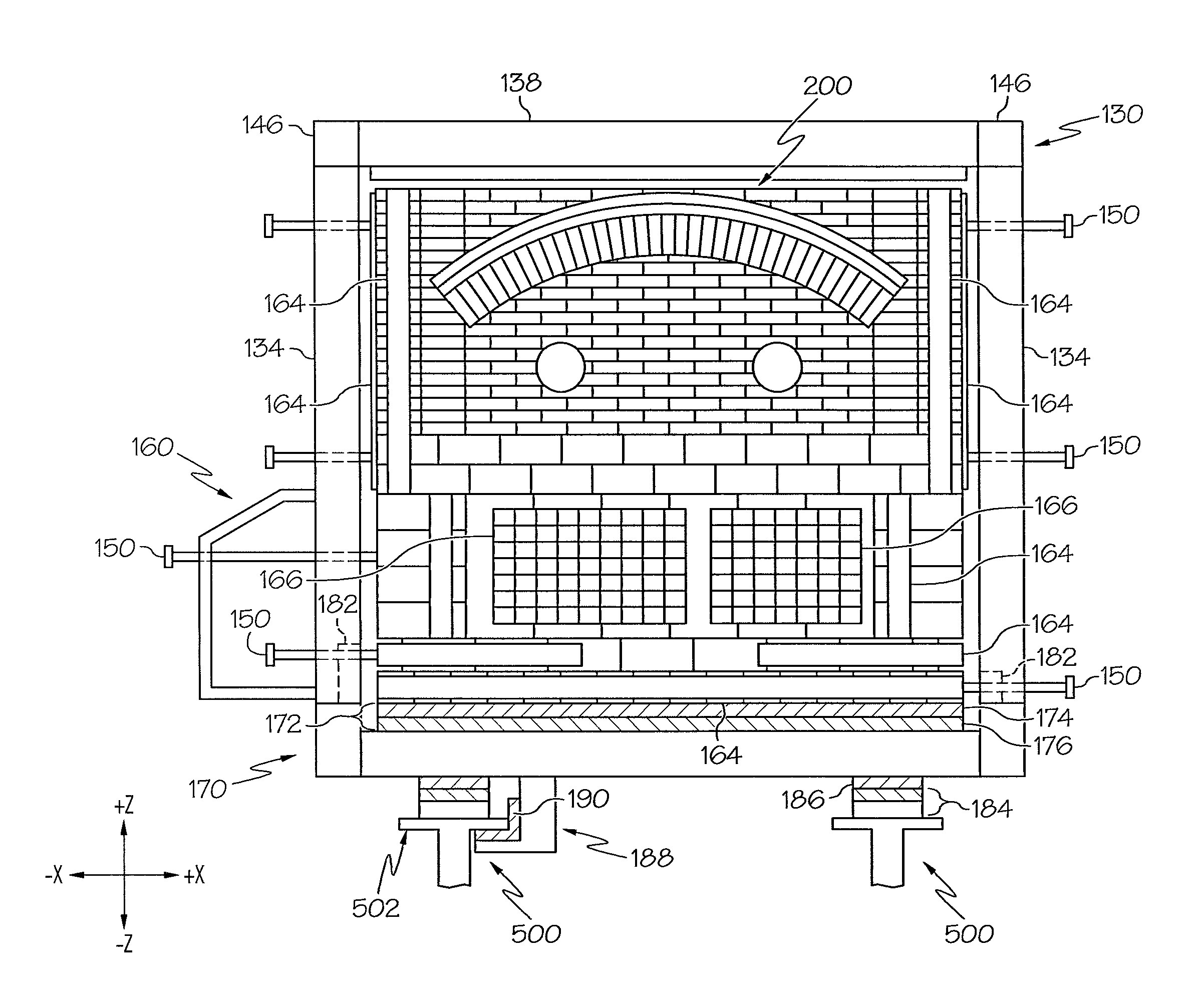
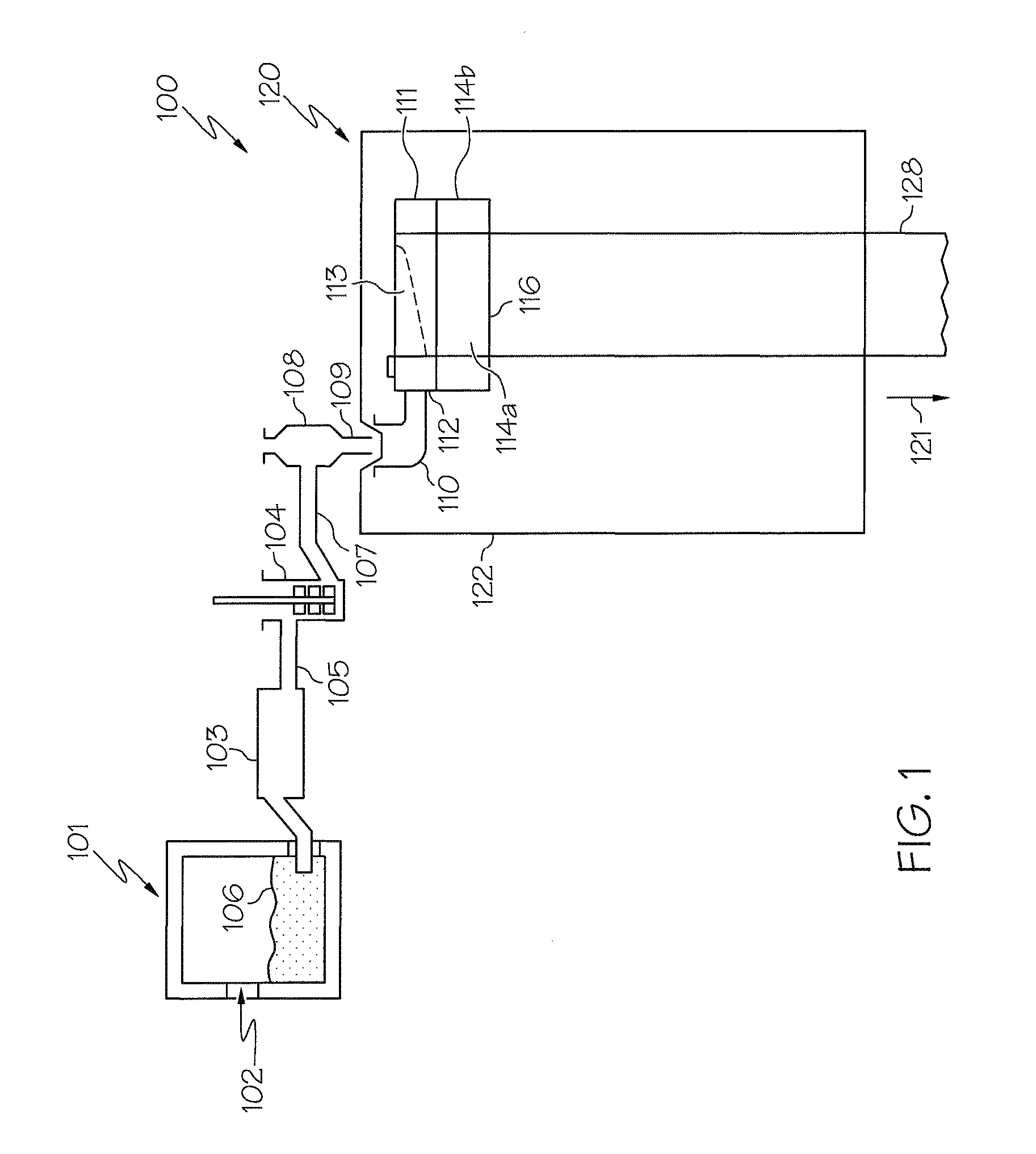
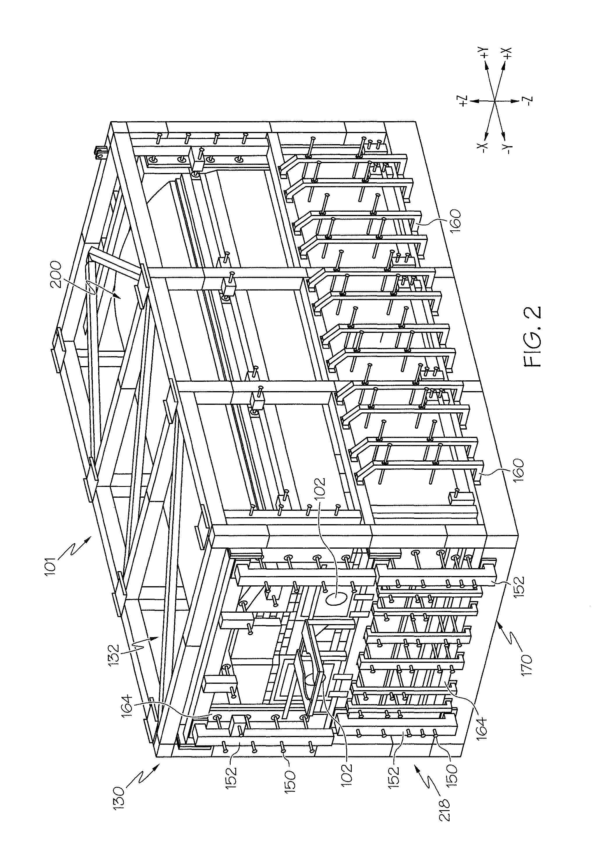
[0022]Reference will now be made in detail to embodiments of melters for glass forming apparatuses, examples of which are illustrated in the accompanying drawings. Whenever possible, the same reference numerals will be used throughout the drawings to refer to the same or like parts. One embodiment of a melter is schematically depicted in FIG. 2. The melter generally comprises a rigid exoskeleton with a base portion, a plurality of upright members and a plurality of cross members which are interconnected such that the upright members and the cross members define an exoskeleton interior volume. A tank assembly may be positioned on the base portion in the exoskeleton interior volume such that the tank assembly is spaced apart from the exoskeleton. A plurality of pressure bolts couple the rigid exoskeleton to the tank assembly. In some embodiments, the melter may have a dynamic resistance greater than about 0.3. The melter and various components of the melter will be described in furthe...


PUM

PropertyMeasurementUnit
temperaturesaaaaaaaaaa
volumeaaaaaaaaaa
electrically insulatingaaaaaaaaaa

Abstract

Melters for glass forming apparatuses and glass forming apparatuses comprising the same are disclosed. According to one embodiment, a melter for melting glass batch materials includes a base portion and a rigid exoskeleton rigidly attached to the base portion and comprising a plurality of upright members interconnected with a plurality of cross members defining an exoskeleton interior volume. Connection nodes formed at intersections of the plurality of cross members with upper ends of the plurality of upright members are constrained from movement relative to the base portion in a longitudinal direction, a transverse direction, and a vertical direction. A tank assembly is positioned on the base portion in the exoskeleton interior volume and coupled to the rigid exoskeleton. In some embodiments, the melter has a dynamic resistance greater than 0.3.

Description

BACKGROUND[0001]1. Field[0002]The present specification generally relates to glass manufacturing apparatuses and, more specifically, to melters for melting molten glass from glass batch materials and glass manufacturing apparatuses comprising the same.[0003]2. Technical Background[0004]Optical quality glass sheets are commonly employed in a variety of optical display devices including LCD displays, LED displays, and the like. Various manufacturing processes may be used to produce the optical quality glass sheets. These manufacturing processes generally involve melting glass precursor materials in ceramic refractory furnaces, and then producing a ribbon of glass from the glass melt by drawing the glass melt from a forming body. Individual glass sheets are then cut from the ribbon of glass. The ribbon can be extraordinarily thin, and movement of the manufacturing equipment during the drawing process (such as from seismic activity or the like) can disrupt the flatness of the glass ribb...

Claims


Application Information

Patent Timeline
Patent Type & Authority Patents(United States)
IPC IPC(8): F27D1/14F27D1/00
CPCF27D1/0003F27D2001/0046C03B5/167C03B5/42F27D1/14Y02P40/57
Inventor FRALEY, RAYMOND EUGENEMANNING, SHAYNE OSAUERS, JASON
Owner CORNING INC
Learn More