Tomography apparatus and tomogram correction processing method
a technology of tomography and processing method, which is applied in the field of tomography apparatus and tomography correction processing method, can solve the problems of difficult to accurately correct positional offset between and lack of feature amounts, and achieve the effect of accurate positional offset correction
- Summary
- Abstract
- Description
- Claims
- Application Information
AI Technical Summary
Benefits of technology
Problems solved by technology
Method used
Image

Examples
first embodiment
1. Arrangement of Tomography Apparatus
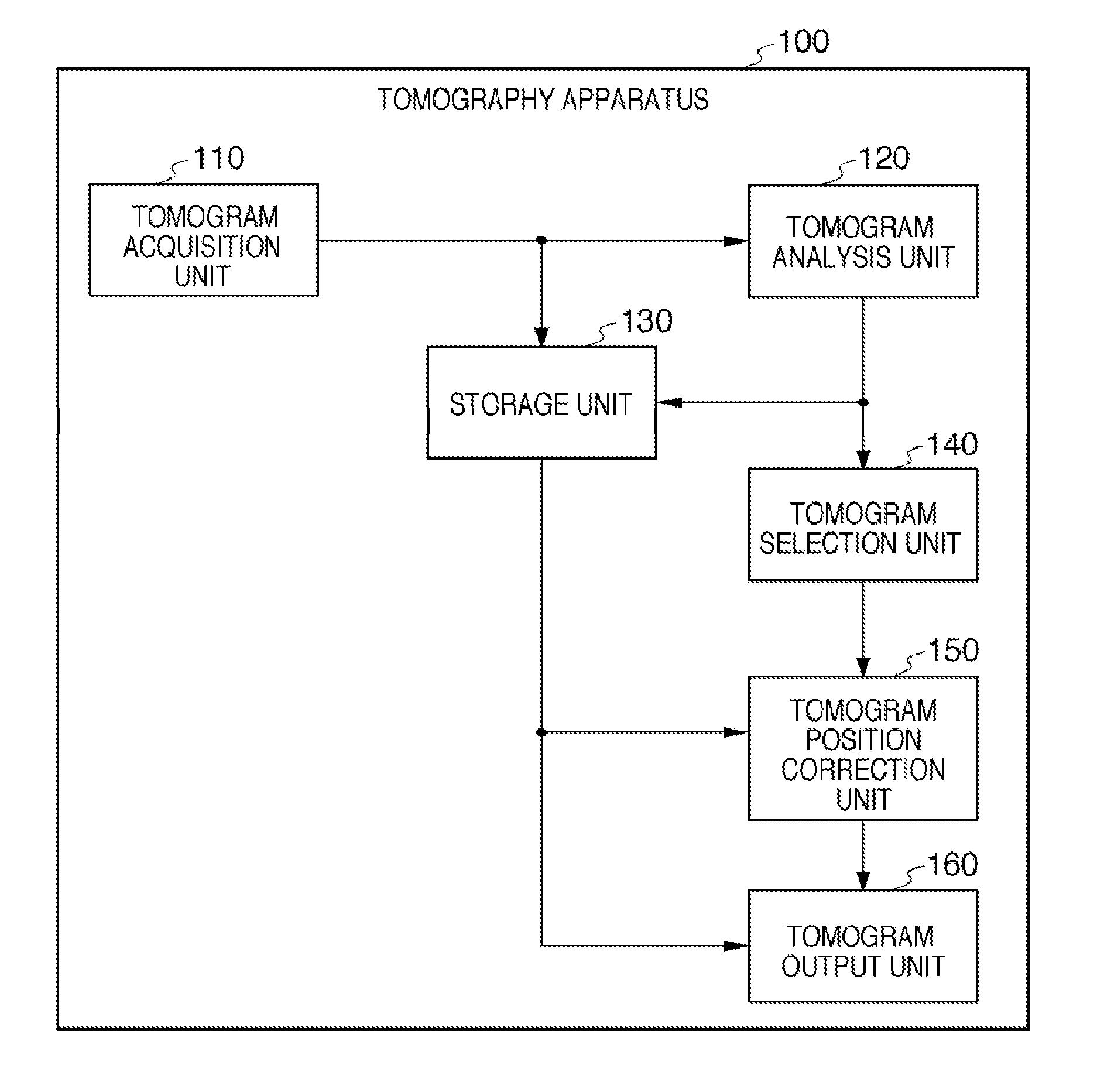
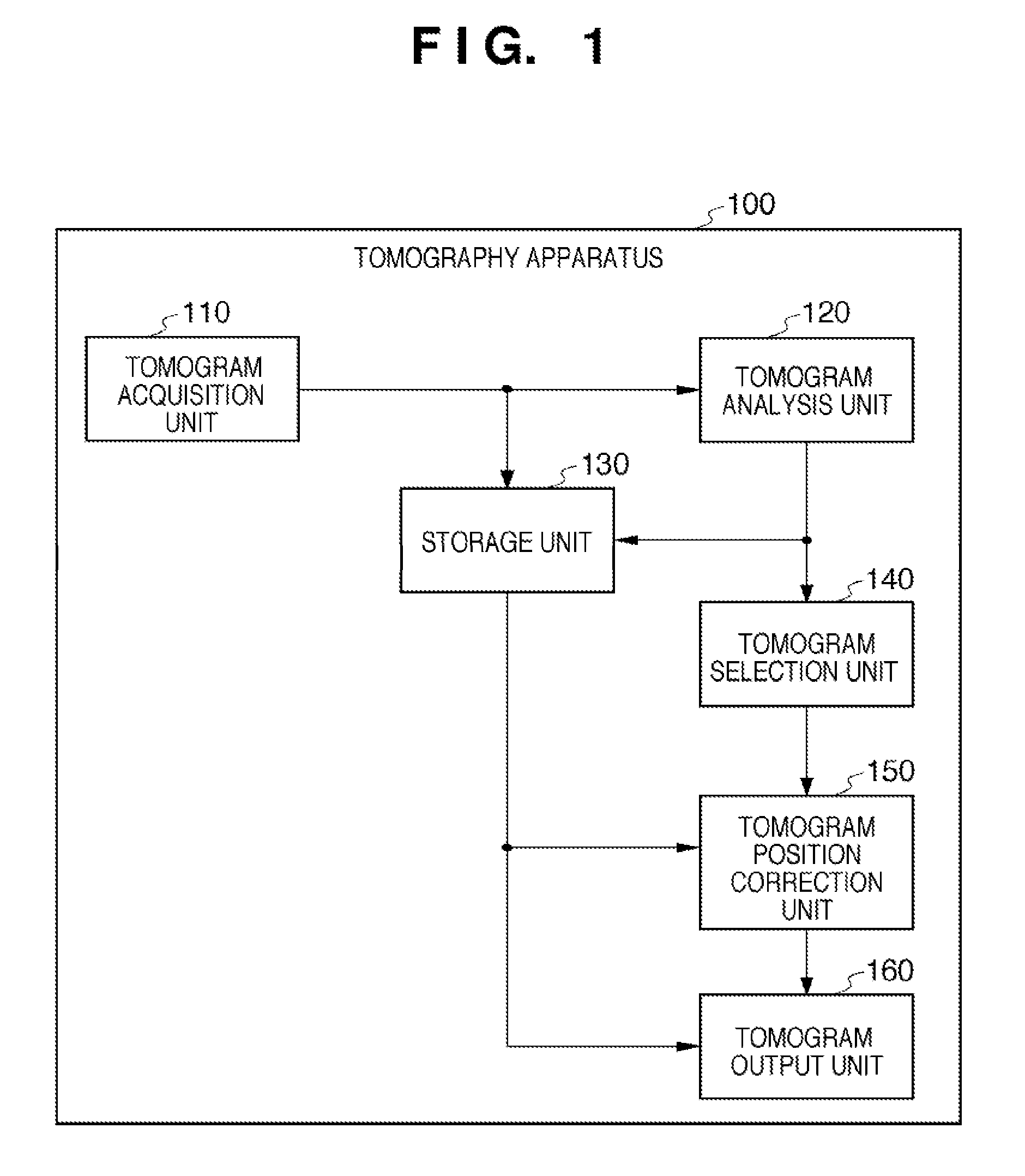
[0040]FIG. 1 is a block diagram showing the overall arrangement of a tomography apparatus 100 according to the first embodiment of the present invention. As shown in FIG. 1, the tomography apparatus 100 includes a tomogram acquisition unit 110, a tomogram analysis unit 120, a storage unit 130, a tomogram selection unit 140, a tomogram position correction unit 150, and a tomogram output unit 160.
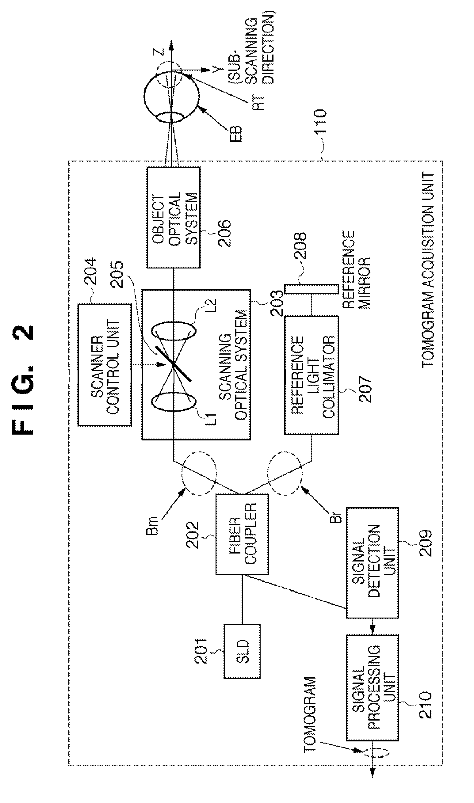
[0041]The tomogram acquisition unit 110 performs imaging processing of a three-dimensional tomogram of a fundus retina as a measurement target. More specifically, the tomogram acquisition unit 110 irradiates the fundus retina with measurement light, and reconstructs a three-dimensional tomogram of the fundus retina by using the interference light obtained by causing interference between reflected light from the fundus retina and reference light. The tomogram acquisition unit 110 will be described in detail later.
[0042]The units ranging from the tomogram a...
second embodiment
[0106]The first embodiment is configured to perform positional offset correction between the respective B-scan images constituting a three-dimensional tomogram by using a B-scan image as a standard tomogram. However, the standard tomogram to be used is not limited to a B-scan image. For example, when simultaneously capturing a plurality of three-dimensional tomograms by simultaneously applying a plurality of measurement light beams which are scanned in conjunction with each other (integrally), one of the three-dimensional tomograms may be selected as a standard tomogram. Assume that in this case, the method described in the first embodiment is used to correct positional offsets between the respective B-scan images constituting a three-dimensional tomogram selected as a standard tomogram (standard three-dimensional tomogram). Assume also that the positional offset correction is performed for three-dimensional tomograms other than the standard three-dimensional tomogram by using the r...
third embodiment
[0153]The second embodiment is configured to select one standard three-dimensional tomogram suitable for positional offset correction. In general, however, the feature amounts in a three-dimensional tomogram are not uniform, and are offset in value. For this reason, the accuracy of positional offset correction may degrade in a region having a small feature amount even in a standard three-dimensional tomogram. A standard three-dimensional tomogram may include a region exhibiting a smaller feature amount than a corresponding region in another three-dimensional tomogram.
[0154]This embodiment therefore segments each of a plurality of three-dimensional tomograms into a plurality of regions, selects a region exhibiting a large feature amount as a standard region tomogram, and performs positional offset correction for corresponding regions in other three-dimensional tomograms based on the standard region tomogram.
[0155]Since the basic arrangement of a tomography apparatus according to this...
PUM
 Abstract
Description
Claims
Application Information
 - R&D
- Intellectual Property
- Life Sciences
- Materials
- Tech Scout
- Unparalleled Data Quality
- Higher Quality Content
- 60% Fewer Hallucinations
Browse by: Latest US Patents, China's latest patents, Technical Efficacy Thesaurus, Application Domain, Technology Topic, Popular Technical Reports.
© 2025 PatSnap. All rights reserved.Legal|Privacy policy|Modern Slavery Act Transparency Statement|Sitemap|About US| Contact US: help@patsnap.com