Method for manufacturing a multi-layer composite, arrangement for positioning a sheet-like element onto a backing in a laminating unit

a multi-layer composite and laminating unit technology, applied in the direction of lamination, mechanical control devices, labelling, etc., can solve the problems of loss of quality, damage to the frontal and lateral edges, and incorrect lengths of corrugated web cutting, etc., to achieve high speed

Active Publication Date: 2015-04-21
ASITRADE
View PDF4 Cites 0 Cited by
  • Summary
  • Abstract
  • Description
  • Claims
  • Application Information

AI Technical Summary

Benefits of technology

[0021]It is a main objective of the present invention to develop a method for manufacturing a multi-layer composite by laminating a sheet-like element onto a backing. A second objective is to develop a laminating method in which a position of the sheet-like elements is adjusted precisely and rapidly. A third objective is to produce an arrangement that allows a positional offset of the sheet-like elements to be corrected without entailing a stoppage phase for subsequent lamination. A fourth objective is to provide a positioning arrangement for a laminating unit that avoids the problems of the prior art. Yet another objective is to create a laminating unit that has an arrangement that operates at high speed and that allows a positioning and correction of the sheets.

Problems solved by technology

This approach inevitably leads to damage to the frontal and lateral edge at the end stops and therefore to a loss of quality.
However, with such a method, the topsheets reach the positioning roll and then the laminating roll in a position that may prove inappropriate.
These misaligned sheets are bonded onto the single-face corrugated web with an offset, and this is undesirable in terms of the quality of the multi-layer composite that is supposed to be obtained.
Further, with such a method, the front edge and rear edge of the topsheet are identified incorrectly, these not being perpendicular to the central longitudinal axis of the laminating machine.
This leads to incorrect lengths when cutting the corrugated web.
However, such successive angular corrections demand that the sheet be moved longitudinally over a long length.
The corrections are incomplete and are therefore imprecise with sheets of small sizes, the latter arriving in quick succession one after another.
Conversely, the corrections are incomplete and therefore imprecise for sheets of larger dimensions because of the larger angles of pivoting to be corrected and because of the inertia of the sheets that has to be overcome.
In addition, these corrections through successive angular movements take time and are therefore incompatible with an increase in overall production rates.
The sheets have a particularly smooth surface and are not effectively corrected by these successive angular adjustments.

Method used


Image

  • Method for manufacturing a multi-layer composite, arrangement for positioning a sheet-like element onto a backing in a laminating unit
  • Method for manufacturing a multi-layer composite, arrangement for positioning a sheet-like element onto a backing in a laminating unit
  • Method for manufacturing a multi-layer composite, arrangement for positioning a sheet-like element onto a backing in a laminating unit

Examples


Embodiment Construction

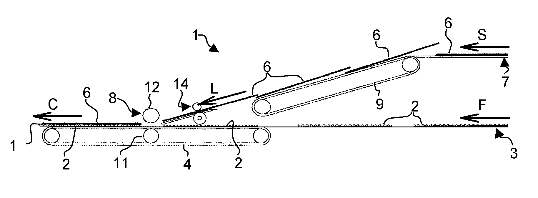
[0051]As shown in FIG. 1, a machine for producing a multi-layer composite comprises a laminating unit (1). The unit (1) can be arranged for instance at the exit of a corrugating machine (not shown) that produce a single-face corrugated web. The unit (1) can also be fed by an unwinder (not shown), if the single-face corrugated web comes from a reel. The single-face corrugated web is then cut into a cutting section (not shown) to produce individual backings (2). The unit (1) can also comprise a feed section (not shown) for the individual backings (2). The feed section is for example, in the form of a board feeder, the individual backings (2) being initially arranged in a pile. This type of assembly is known as being a sheet-to-sheet laminator.

[0052]The backings (2) are supplied continuously from the longitudinal upstream direction downstream (Arrow F) by a first conveying section (3), for example in the form of a first endless belt. At this stage, the unit (1) comprises an adhesive-co...


PUM

PropertyMeasurementUnit
angleaaaaaaaaaa
conveying speedaaaaaaaaaa
bonding speedaaaaaaaaaa

Abstract

A method and an arrangement for manufacturing a multi-layer composite (13) by laminating a sheet-like element (6) onto a backing (2) in a laminating unit (1), having steps, in this order, of conveying the element (6) in a longitudinal direction, detecting a position of the element (6), correcting the position of the element (6) on the basis of the detected position and on the basis of a reference position (15), and bonding said element (6) onto the backing (2). The detection step comprises the phases of measuring the lateral position, an angle of pivoting, and a longitudinal position of the element (6), and the correction step includes phases of lateral movement (T), pivoting (P), and longitudinal movement (L) of the element (6), apparatus elements perform the steps.

Description

BACKGROUND OF THE INVENTION[0001]The present invention relates to a method for manufacturing a multi-layer composite by laminating a sheet-like element onto a backing in a laminating unit. The invention also relates to an arrangement for positioning a sheet-like element onto a backing, to manufacture a multi-layer composite in a laminating unit. The invention relates to a laminating unit for manufacturing a multi-layer composite embodying such a method and comprising such a positioning arrangement.[0002]Multi-layer composite materials are used in the field of packaging, after they have been cut, folded and glued. One of these composites commonly used is corrugated board. It is used mainly as a protective packaging that is particularly strong while being readily recyclable.[0003]Corrugated board is for example made up of an inner board provided with corrugations, bonded onto a first flat coverboard on one side of the corrugations. This inner board with first flat coverboard constitut...

Claims


Application Information

Patent Timeline
Patent Type & Authority Patents(United States)
IPC IPC(8): B32B41/00B32B38/18
CPCB32B38/1833B32B41/00B32B2041/04B32B2317/12
Inventor MAYER, THOMASMANN, ALEXSIEGENTHALER, MICHELGUGLIELMETTI, PHILIPPE
Owner ASITRADE
Why Eureka
Try Eureka