Method and apparatus for evaluating a sample through variable angle Raman spectroscopy

a raman spectroscopy and sample technology, applied in the direction of optical radiation measurement, instruments, spectrometry/spectrophotometry/monochromators, etc., can solve the problems of relatively small laser light scattering inelastically, current raman spectroscopy systems are relatively limited in their ability to interact with samples at different depths, and system efficiency is relatively low

Inactive Publication Date: 2015-03-03
AVOLONTE HEALTH
View PDF91 Cites 7 Cited by
  • Summary
  • Abstract
  • Description
  • Claims
  • Application Information

AI Technical Summary

Benefits of technology

[0004]The methods and apparatus described herein provide a novel methodology for variable angle Raman spectroscopy, in which an excitation beam of electromagnetic radiation will be caused to intersect the sample under investigation at a plurality of angles of incidence, so as to provide Raman scattering spectra at each angle. In most examples, the excitation beam will be a single wavelength. In some examples, multiple excitation beams, each at a single wavelength, may be used to excite the sample to induce the Raman scattering. One example use of measuring such spectra at multiple angles of incidence is to enable evaluation at a plurality of depths within the sample. In many examples, the range of the plurality of angles of incidence utilized will be very near the critical angle of incidence; and thus, such methods may be termed “peri-critical Raman spectroscopy.” In many examples as described herein, the range of the angles of incidence will include, and extend to either side of, the critical angle.

Problems solved by technology

However, a relatively small portion of the laser light is scattered inelastically as a result of coming into contact with the sample.
A limitation of current Raman spectroscopy systems is a relatively limited capability to interact with a sample at different depths into the sample.
However, these systems are relatively inefficient; and in view of the relatively small amount of Raman scattering signal that is typically available, will not be well-suited to some applications.

Method used


Image

  • Method and apparatus for evaluating a sample through variable angle Raman spectroscopy
  • Method and apparatus for evaluating a sample through variable angle Raman spectroscopy
  • Method and apparatus for evaluating a sample through variable angle Raman spectroscopy

Examples


Embodiment Construction

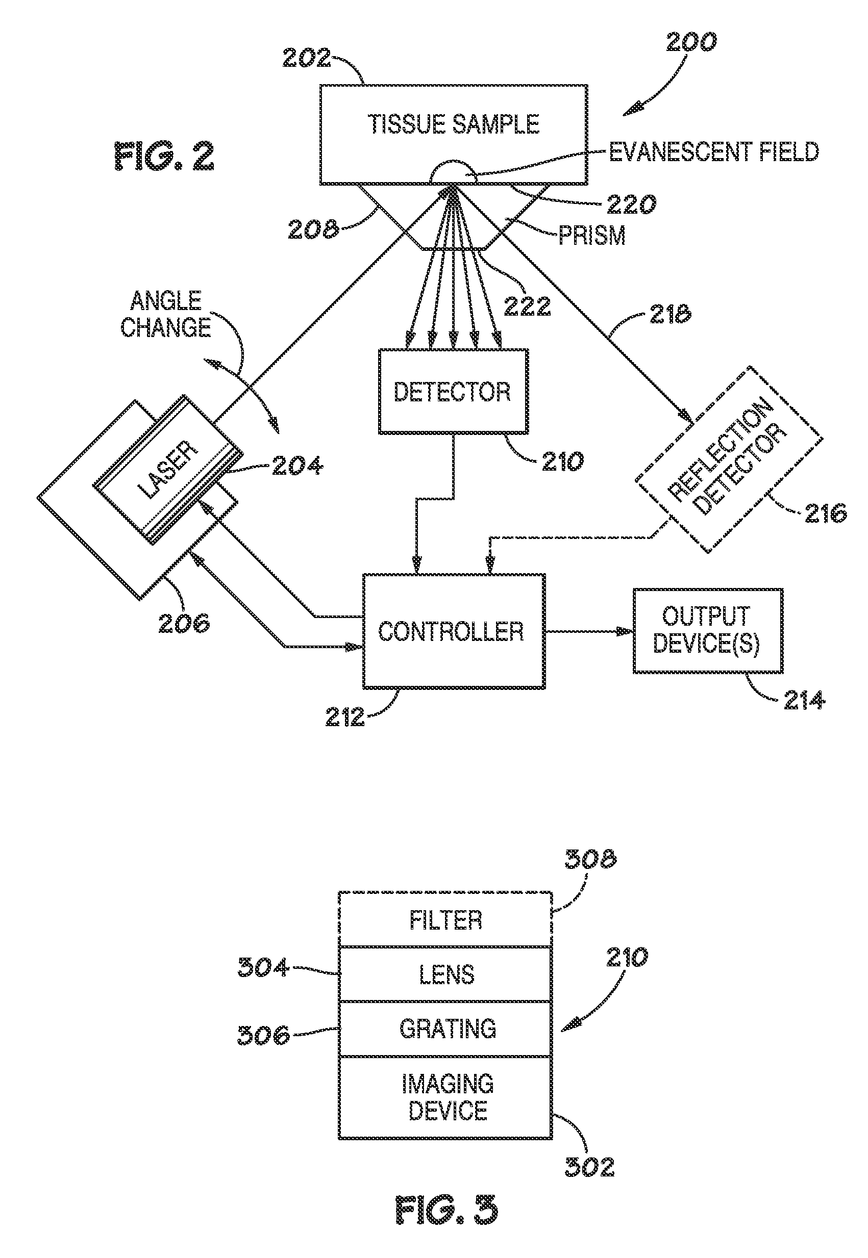
[0011]The following detailed description refers to the accompanying drawings that depict various details of examples selected to show how the present invention may be practiced. The discussion addresses various examples of the inventive subject matter at least partially in reference to these drawings, and describes the depicted embodiments in sufficient detail to enable those skilled in the art to practice the invention. Many other embodiments may be utilized for practicing the inventive subject matter than the illustrative examples discussed herein, and many structural and operational changes in addition to the alternatives specifically discussed herein may be made without departing from the scope of the inventive subject matter.

[0012]In this description, references to “one embodiment” or “an embodiment,” or to “one example” or “an example” mean that the feature being referred to is, or may be, included in at least one embodiment or example of the invention. Separate references to ...


PUM

PropertyMeasurementUnit
critical angleaaaaaaaaaa

Abstract

Described are systems and methods for variable angle Raman spectroscopy, in which electromagnetic radiation will be caused to intersect the sample under investigation at a plurality of angles of incidence, so as to provide Raman scattering spectra at each angle. One example use of measuring such spectra at multiple angles of incidence is to enable evaluation at a plurality of depths within the sample. In many implementations, the range of the angles of incidence will include, and extend to either side, of the critical angle.

Description

[0001]The present invention relates generally to the evaluation of samples through use of Raman spectroscopy adapted to direct electromagnetic radiation to intersect the sample at a plurality of angles; and more particularly relates to such methods wherein the Raman scattered electromagnetic radiation from a plurality of angles of incidence is used to evaluate one or more properties of the sample under investigation.BACKGROUND OF THE INVENTION[0002]In conventional Raman spectroscopy, a source of electromagnetic radiation, such as a laser, will be used to excite a sample under investigation with an excitation energy. After contacting the sample, the excitation energy will be scattered. Most of the light scattered by the sample will be scattered elastically; this light is at an unshifted wavelength and may be detected after leaving the specimen. However, a relatively small portion of the laser light is scattered inelastically as a result of coming into contact with the sample. This in...

Claims


Application Information

Patent Timeline
Patent Type & Authority Patents(United States)
IPC IPC(8): G01J3/44G01N21/47G01N21/65
CPCG01N21/65G01N2021/4704
Inventor MESSERSCHMIDT, ROBERT G.
Owner AVOLONTE HEALTH
Why Eureka
Try Eureka