Radiation image pickup apparatus and method of driving the same
a technology of image pickup and apparatus, which is applied in the direction of radioation control devices, instruments, television systems, etc., can solve the problem of difficulty in performing correct photoelectric conversion (image pickup) of radiation corresponding to incident energy
- Summary
- Abstract
- Description
- Claims
- Application Information
AI Technical Summary
Benefits of technology
Problems solved by technology
Method used
Image
Examples
first embodiment (
1. First Embodiment (radiation image pickup apparatus)
2. Descriptions of functions and effects
3. Modifications
4. Second Embodiment
FIRST EMBODIMENT
System Configuration
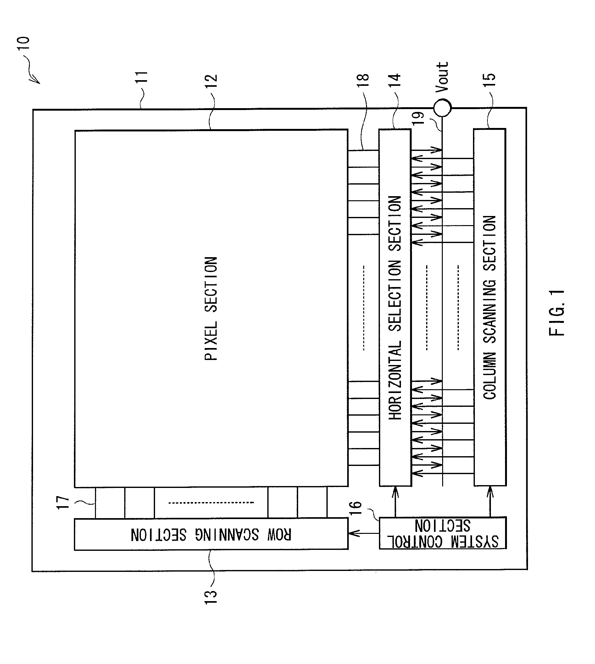
[0030]FIG. 1 illustrates a system configuration of a photoelectric conversion device 10 of a radiation image pickup apparatus according to a first embodiment of the invention. The radiation image pickup apparatus is configured by arranging a wavelength converter 40 (refer to FIG. 3) on the photoelectric conversion device 10, and reads information based on radiation by converting the wavelength of radiation represented by α-rays, β-rays, γ-rays or X-rays.
[0031]The photoelectric conversion device 10 includes a pixel section 12 on a substrate 11 made of an insulating material such as glass, and a peripheral circuit section (drive section) including, for example, a row scanning section (vertical drive section) 13, a horizontal selection section 14, a column scanning section (horizontal drive section) 15 and a system control...
second embodiment
[0073]In the above-described embodiment, an example in which the drive circuit of the pixel is configured of an active drive circuit is described, but the drive circuit of the pixel may be a passive drive circuit as illustrated in FIG. 10. Note that like components are denoted by like numerals as of the above-described embodiment and will not be further described.
[0074]In the embodiment, a unit pixel 90 is configured of the photoelectric conversion element 21, the capacity component 25 and a read transistor 91. The read transistor 91 is connected between the storage node N and the vertical signal line 18, and when the read transistor 91 turns on in response to the row scanning signal Vread, the read transistor 91 transmits a signal charge accumulated in the storage node N to the vertical signal line 18.
[0075]An end of the vertical signal line 18 is connected to an input terminal 92b of a measurement charge amplifier 92 having another internal terminal 92a connected to a ground. The ...
PUM
 Abstract
Description
Claims
Application Information
 - R&D
- Intellectual Property
- Life Sciences
- Materials
- Tech Scout
- Unparalleled Data Quality
- Higher Quality Content
- 60% Fewer Hallucinations
Browse by: Latest US Patents, China's latest patents, Technical Efficacy Thesaurus, Application Domain, Technology Topic, Popular Technical Reports.
© 2025 PatSnap. All rights reserved.Legal|Privacy policy|Modern Slavery Act Transparency Statement|Sitemap|About US| Contact US: help@patsnap.com


