Dynamic de-icing distance

a technology of de-icing distance and nozzle, which is applied in the direction of distance measurement, instruments, and using re-radiation, etc., can solve the problems of reducing the ability of aircraft wings to generate lift force, ice may prevent important control surfaces, such as flaps and elevators, from operating properly, and the distance between the nozzle and the aircraft body or the aircraft wing is not considered, so as to reduce the amount of de-icing fluid used and the time needed for de-icing

Active Publication Date: 2015-03-03
VESTERGAARD CO AS
View PDF18 Cites 2 Cited by
  • Summary
  • Abstract
  • Description
  • Claims
  • Application Information

AI Technical Summary

Benefits of technology

[0006]An object according to the present invention is to achieve a more efficient de-icing of aircraft wings. An advantage according to the present invention is that it allows for a reduction of the amount of de-icing fluid used and of the time needed for de-icing. A particular feature of the present invention is that it allows for a de-icing that takes the distance between the nozzle applying the de-icing fluid and the wing surface into account when controlling the position of the nozzle. An additional object according to the present invention is to provide safer de-icing techniques avoiding or reducing the risk for accidents to occur.SUMMARY / DISCLOSURE OF INVENTION
[0007]The above object, the above advantage and the above feature, together with numerous other objects, advantages and features, will be evident from the detailed descriptions given below of preferred embodiments according to the present invention. The objects, advantages and features are according to a first aspect of the present invention obtained by a method for at least partially de-icing an aircraft by applying a de-icing fluid through a nozzle, the method comprising the steps of: measuring a first distance along a measurement direction from a first location relative to the nozzle to a physical outside surface of the aircraft, applying the first distance in a first evaluation, controlling the position and / or the orientation of the nozzle according to the first evaluation, and applying the de-icing fluid to at (east a part of the physical outside surface trough the nozzle.

Problems solved by technology

Ice may degrade the ability of an aircraft wing to generate a lift force.
For an aircraft in self propelled motion, pieces of ice may come loose and cause damage by hitting the tail or tail fins, or by being sucked into an engine or hitting a propeller, which may have catastrophic effects.
Further, ice may prevent important control surfaces, such as flaps and elevators, from operating properly.
However, the distance between the nozzle and the aircraft body or aircraft wing is not considered in the de-icing.

Method used


Image

  • Dynamic de-icing distance
  • Dynamic de-icing distance
  • Dynamic de-icing distance

Examples


Embodiment Construction

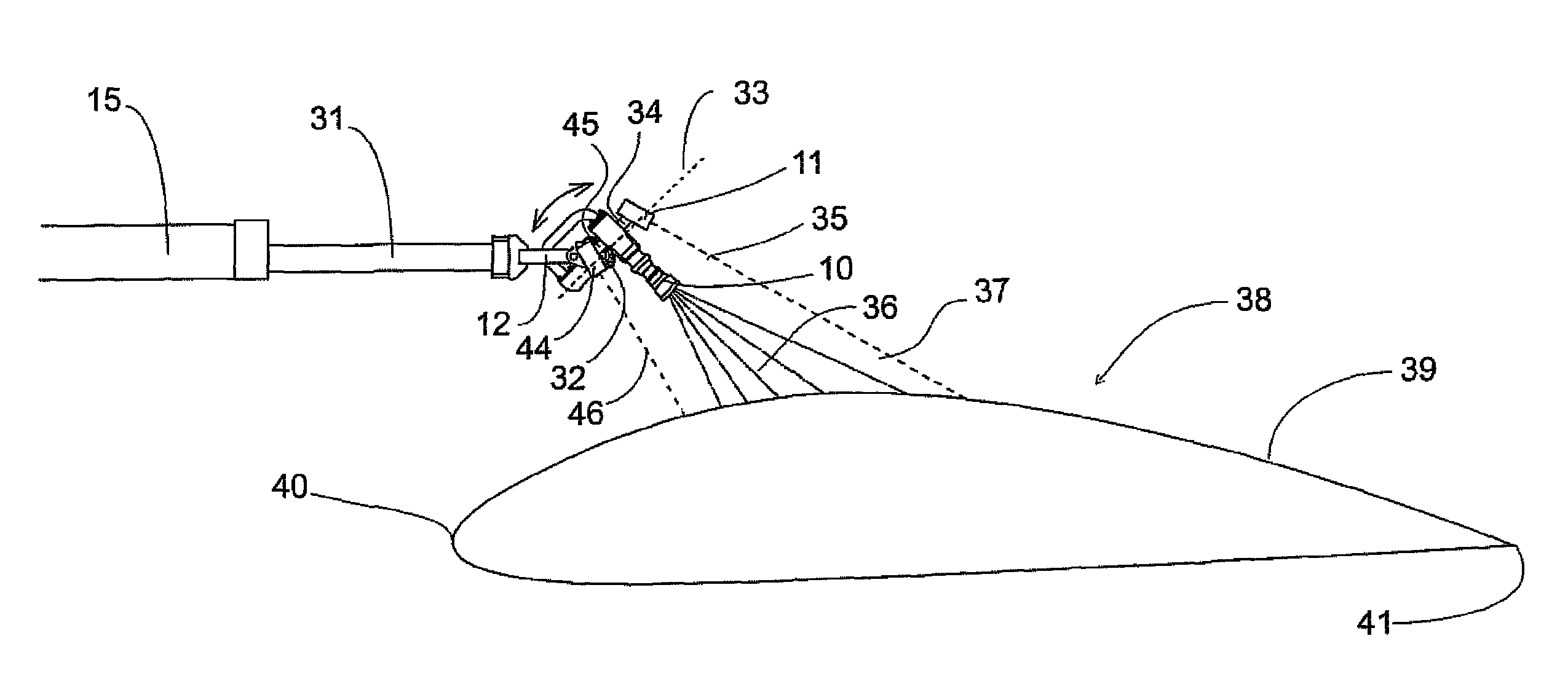
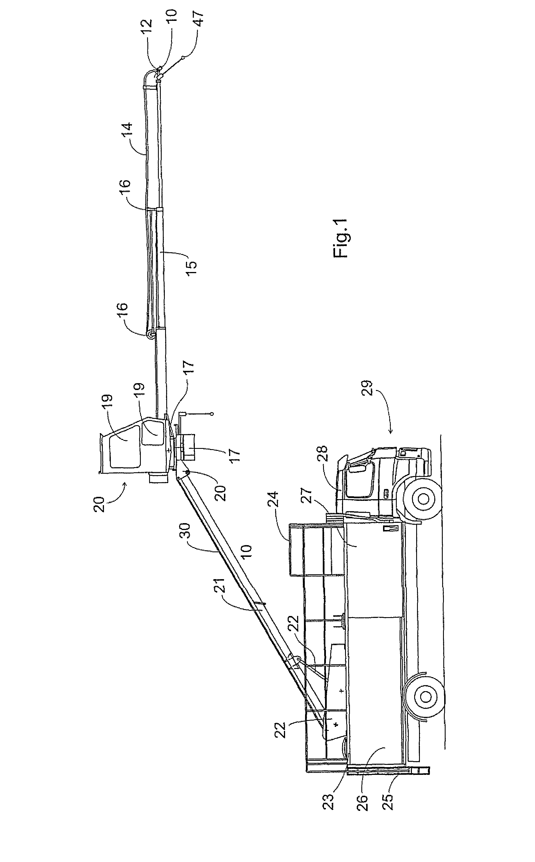
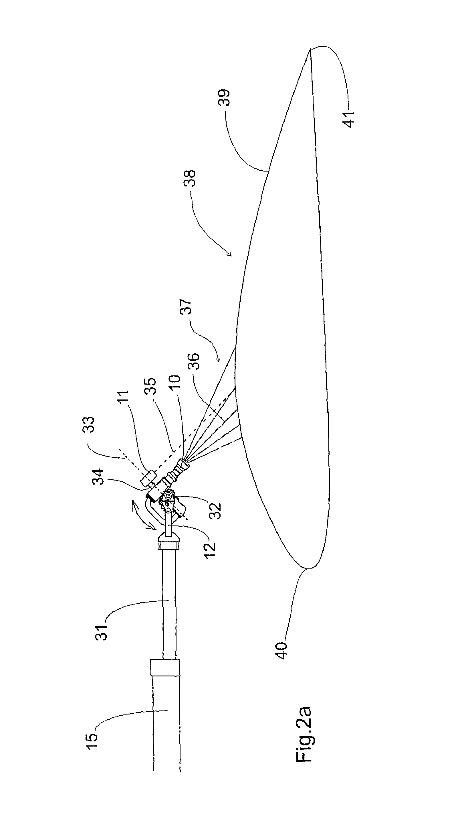
[0078]A preferred embodiment of the proposed system for de-icing is illustrated in FIG. 1. The nozzle 10 for supplying a de-icing liquid is supported by a first pivot support that is attached to an extendable support arm 15. The first pivot support 12 provides an adjustable orientation of the nozzle 10 by a horizontal pivot axis allowing a pivotal motion in a vertical plane embedding the adjustable support arm 15, and a normal pivot axis allowing sideways motions with respect to the extendable support arm 15. The first pivot support 12 is also provided with actuation mechanisms enabling an automated pivotal motion of the nozzle 10. The nozzle is supplied with de-icing liquid via conduits 14. The support arm is provided with conduit supports 16 for preventing a slackening of the conduits 14 when the length of the extendable support arm 15 is changed. The support arm 15 is divided into three segments that can slide with respect to one another, thereby enabling a extension of the suppo...


PUM


Abstract

A method for at least partially de-icing an aircraft by applying a de-icing fluid through a nozzle (10) is disclosed. The method involves the steps of: measuring a distance to an outside surface of the aircraft, applying the distance in an evaluation, controlling the position and / or the orientation of the nozzle (10) according to the evaluation, and applying the de-icing fluid at least a part of the outside surface trough the nozzle. In addition, a system for performing the de-icing method is also revealed.

Description

FIELD OF THE INVENTION[0001]The present invention generally relates to de-icing of an aircraft wing, and in particular to the application of the de-icing fluid. More specifically, the present invention relates to a de-icing method involving a nozzle and a distance sensor, where the latter is employed to determine the distance between the nozzle and the aircraft wing.DESCRIPTION OF THE RELATED ART[0002]Under freezing conditions, the de-icing of an aircraft may be critical for its flight performance. Ice may degrade the ability of an aircraft wing to generate a lift force. For an aircraft in self propelled motion, pieces of ice may come loose and cause damage by hitting the tail or tail fins, or by being sucked into an engine or hitting a propeller, which may have catastrophic effects. Further, ice may prevent important control surfaces, such as flaps and elevators, from operating properly.[0003]Here the term de-icing means the removal of ice or the prevention of ice to form. The term...

Claims


Application Information

Patent Timeline
Patent Type & Authority Patents(United States)
IPC IPC(8): B05B13/04B64D15/10B64F5/00G01S17/48G01S17/88
CPCB64F5/0063G01S17/48G01S17/88B64F5/23
Inventor SVANEBJERG, ELO
Owner VESTERGAARD CO AS
Why Eureka
Try Eureka