Compact low frequency audio transducer

a low-frequency audio and low-frequency technology, applied in the field of loudspeakers or audio transducers, can solve the problems of poor sound reproduction, woofer failure, and generating substantial amounts of hea

Active Publication Date: 2015-02-24
GRAHAM DOUG
View PDF1 Cites 13 Cited by
  • Summary
  • Abstract
  • Description
  • Claims
  • Application Information

AI Technical Summary

Benefits of technology

[0016]In accordance with the present invention, a compact, efficient and powerful low frequency audio transducer design overcomes the problems of the prior art by providing a novel structure for controlling and driving a plurality (e.g., four) gas impermeable diaphragm members or vanes rotating back and forth within a vented tubular chamber or lumen through a selected maximum excursion arc or excursion angle (e.g., 45 degrees), but not in a direct-radiating pistonic motion.

Problems solved by technology

In particular, high power signals driving the cone into extreme excursions cause poor sound reproduction when driven by more challenging audio signals.
Another concern for music aficionados and auto-sound competitors is woofer failure due to thermal or mechanical overloading problems.
Signals having such power require very large current flow through voice coil conductors, thus generating substantial amounts of heat, and drive the woofers to extreme excursions, thus generating extreme mechanical loads on diaphragms and suspensions.
These typical direct radiating low frequency transducer designs have not really proven satisfactory for many audio system designers and audio enthusiasts.
Others have attempted to use rotary or rotating vane structures driven by rotating motor structures such as rotating commentator motors or rotating servomotors (i.e., rotor within stator motors) such as are disclosed in U.S. Pat. Nos. 4,564,727, 4,763,358 (Danley et al) or U.S. Pat. No. 5,825,901 (Hisey), but these low frequency transducer systems have, not found favor in the marketplace, possibly because of the complexity, cost and weight associated with motors having rotating armatures (e.g., rotors) within stators.

Method used


Image

  • Compact low frequency audio transducer
  • Compact low frequency audio transducer
  • Compact low frequency audio transducer

Examples


Embodiment Construction

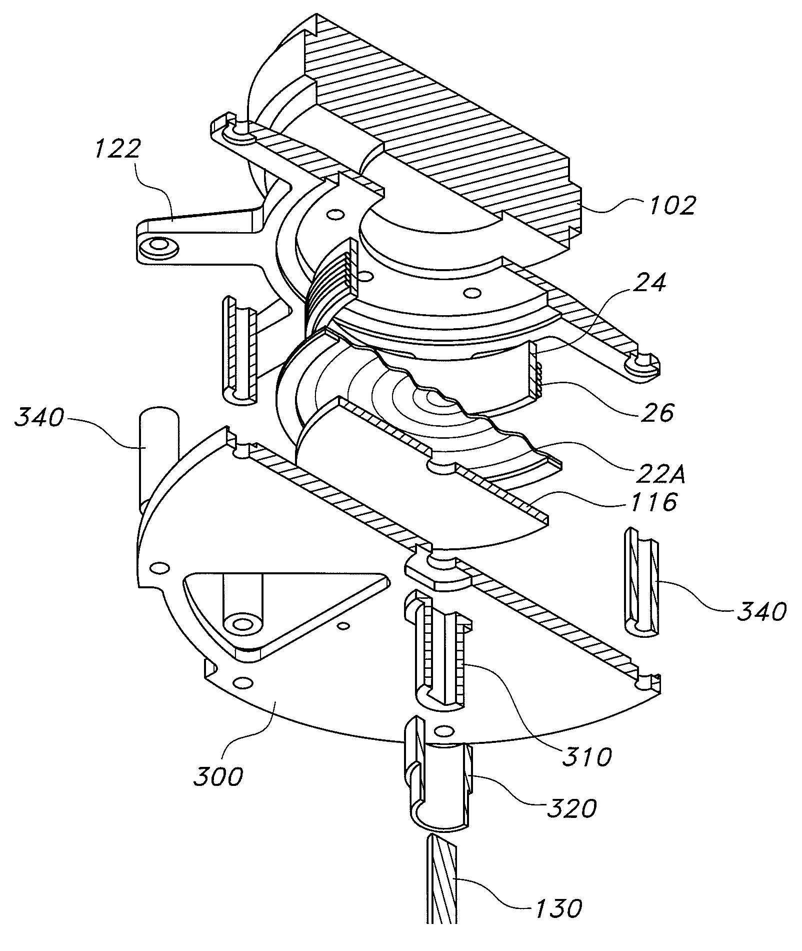
[0047]Turning now to FIGS. 3A-14, the components and configuration of a first embodiment of a bass pump transducer 100 are illustrated, in accordance with the present invention. Compact bass pump transducer 100 uses at least one, and preferably two opposing linear reciprocating electrodynamic motor structures 102, 104 configured to drive a push-pull reciprocating gear or worm gear to rotate a shaft which in turn applies controlled rotation force to each vane.

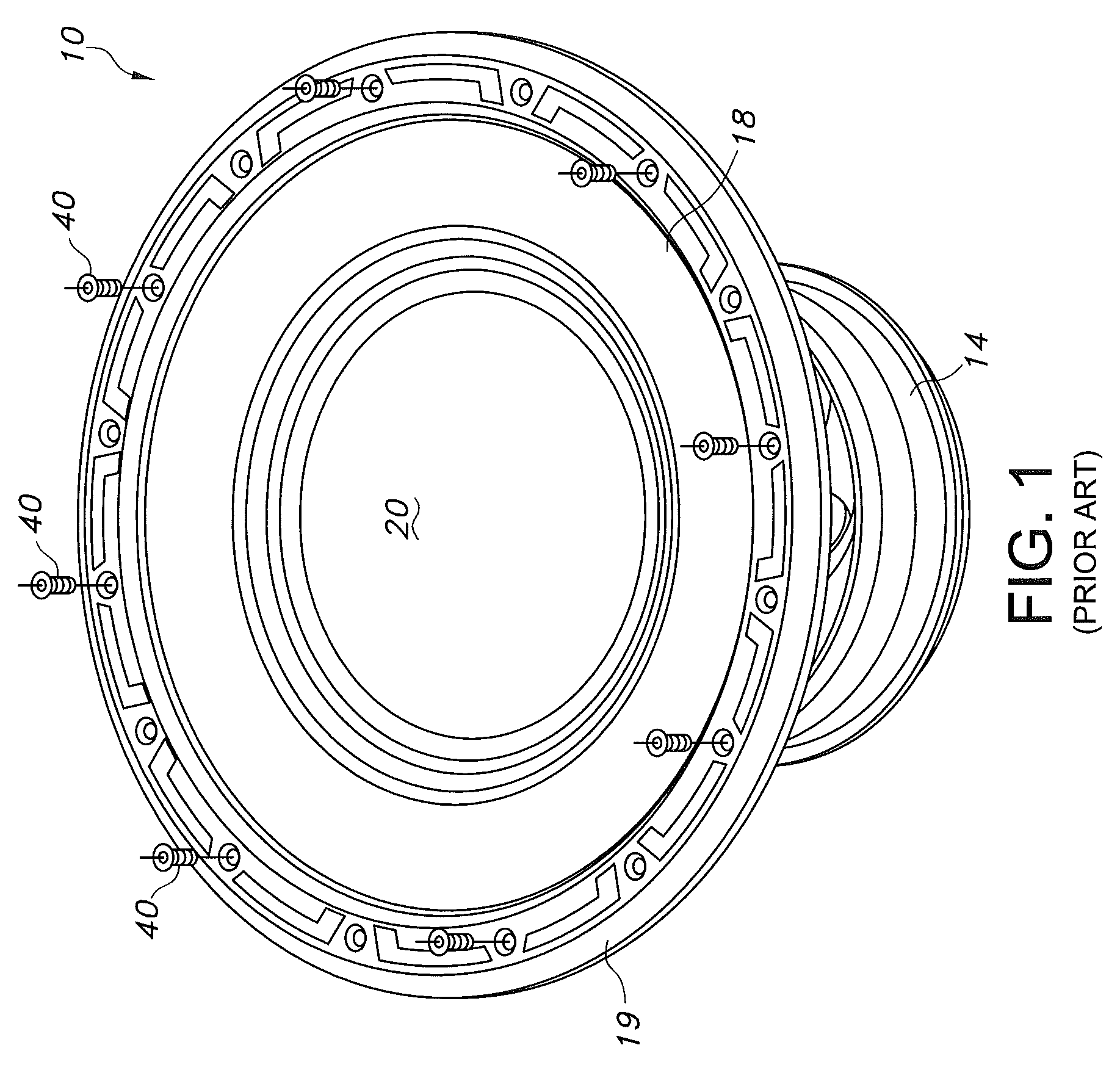
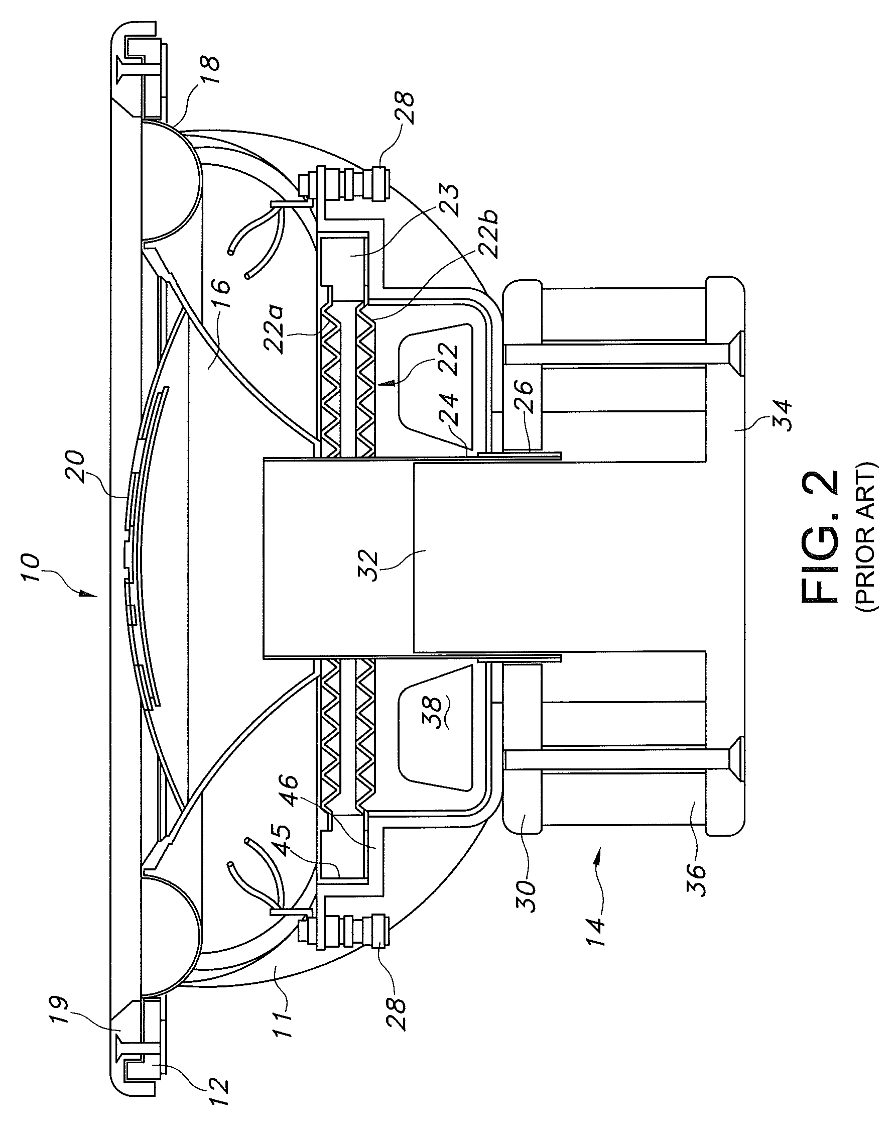
[0048]Electrodynamic motor structures 102, 104 resemble the standard woofer motor 14 illustrated in FIGS. 1 and 2, but are used to drive a very different kind of air displacement mechanism. Thus, electrodynamic motor structures 102, 104 may each include at least one electrically conductive voice coil 26 having two ends (plus and minus) is wound around voice coil former 24; the voice coil ends (plus and minus) are each electrically connected to a single terminal connector 28 by a releasable electrical connection. Optionally, firs...


PUM


Abstract

A rotary reciprocating acoustic transducer for producing sound in response to an applied electrical signal has a ported tubular housing having a generally cylindrical chamber with an interior lumen which is generally symmetrical about a central axis and opposing first and second linear reciprocating electrodynamic motors mounted over the tubular housing member's first and second open end, with a reciprocating rotatable transducer vane assembly with first and second rotating vanes projecting radially away from a central, axially aligned shaft driven by the first and second linear reciprocating motors.

Description

REFERENCE TO PRIOR APPLICATIONS[0001]This application claims the benefit of prior copending U.S. Provisional Application No. 61 / 728,418 filed Nov. 20, 2012, the entire disclosure of which is hereby incorporated herein by reference.BACKGROUND OF THE INVENTION[0002]1. Field of the Invention[0003]The present invention relates to loudspeakers or audio transducers and more particularly to Subwoofers, as used in audio playback and sound reinforcement applications.[0004]2. Discussion of the Prior Art[0005]A great variety of moving coil loudspeaker transducer designs have been proposed for high quality, low frequency sound reproduction. Low frequency transducers or “woofers” are typically included in a modern full range loudspeaker system utilizing different transducers for different segments of the sound spectrum. For example, the “woofer” is used for bass or low frequencies, a mid-range speaker is used for intermediate frequencies and a “tweeter” is used for the highest frequencies in the...

Claims


Application Information

Patent Timeline
Patent Type & Authority Patents(United States)
IPC IPC(8): H04R1/20H04R25/00F01N13/00H04R1/28H04R9/06
CPCH04R9/06H04R1/2811
Inventor GRAHAM, DOUG
Owner GRAHAM DOUG
Why Eureka
Try Eureka