
Offset cup impactor with a grasping plate for double mobility implants

a technology of acetabular implants and impactors, which is applied in the field of surgical inserters, can solve the problems of difficult cleaning, difficult control, and difficult cleaning of complicated mechanical devices, and achieve the effects of reducing the possibility of cup damage, minimizing stress, and reducing the possibility of implantation procedur

Active Publication Date: 2015-02-24
VIANT AS&O HLDG LLC
View PDF131 Cites 1 Cited by
  • Summary
  • Abstract
  • Description
  • Claims
  • Application Information

AI Technical Summary

Benefits of technology

The inserter minimizes damage to the implant during insertion, facilitates precise control and positioning, and enhances sterilization by reducing crevices and blind holes, thereby reducing the risk of structural deformation and wear, and improving surgical efficiency.

Problems solved by technology

Double mobility implants, on the other hand, do not have such an opening and therefore create a challenge in controlling them during implantation.
Complicated mechanical devices have crevices and recesses that are difficult, if not almost impossible to clean with ease.
Devices that are not properly cleaned and sterilized run the risk of disease transfer from patient to patient following the emergence of certain “prions” that are not killed by normal hospital sterilization and need to be physically removed by washing and rinsing.
The application of such mechanical impacting forces could damage the implant cup, particularly a double mobility prosthetic cup implant since these types of cup implants generally lack the mechanical strength to withstand the application of these forces throughout the prosthetic cup.
Furthermore, these double mobility prosthetic cups are precisely machined with smooth surfaces and as such, these implants could become structurally deformed, cracked or scratched during implantation.
Such damage to the cup could result in a decrease of mobility for the patient or the need to repeat the prosthetic cup implantation process.
The damage could also increase the risk of higher wear rates from the bearing components leading to possible earlier device failure.
Further, in surgical procedures in which access to the treatment site is limited, it is difficult to use current solutions without subjecting the patient to repeated abrasion and tissue trauma when inserting, operating and extracting surgical instruments.
Still further, once the appropriate position of the implant is selected, it is often difficult to ensure that the position does not change upon insertion of the assembly through the incision.

Method used


Image

  • Offset cup impactor with a grasping plate for double mobility implants
  • Offset cup impactor with a grasping plate for double mobility implants
  • Offset cup impactor with a grasping plate for double mobility implants

Examples


Embodiment Construction

)

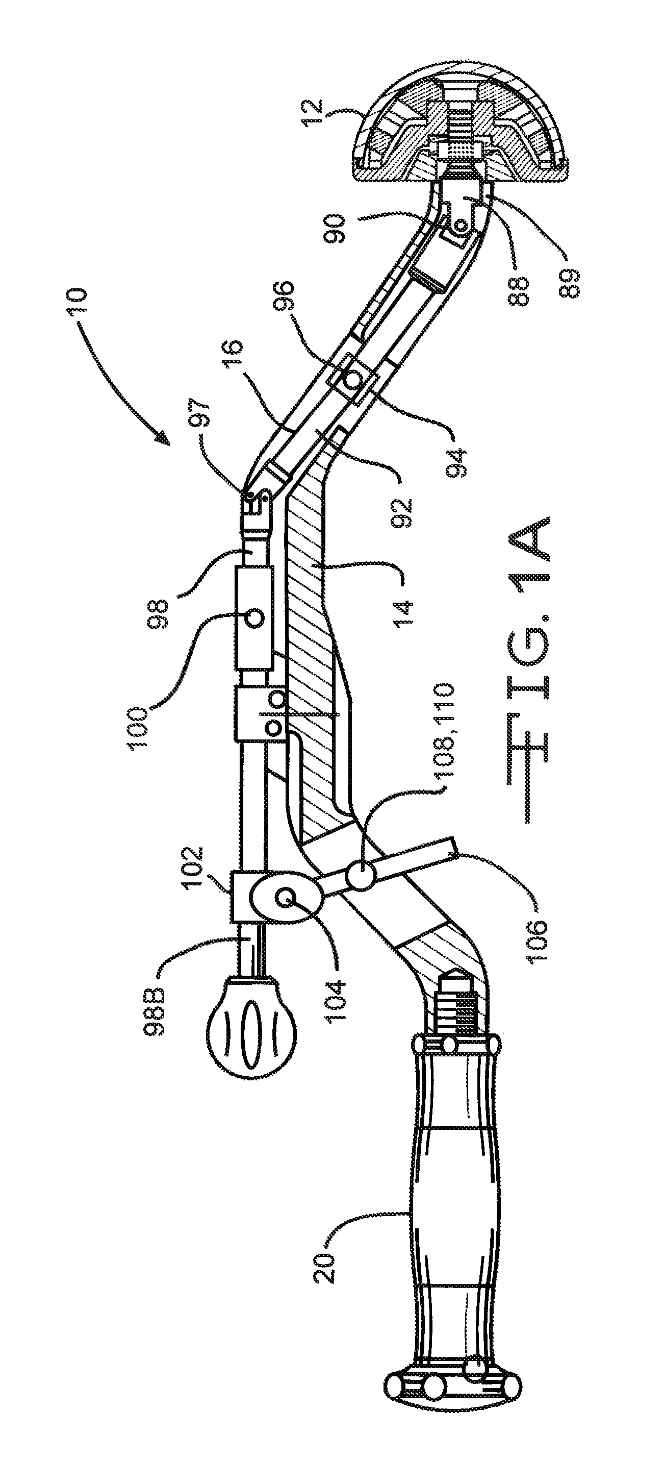
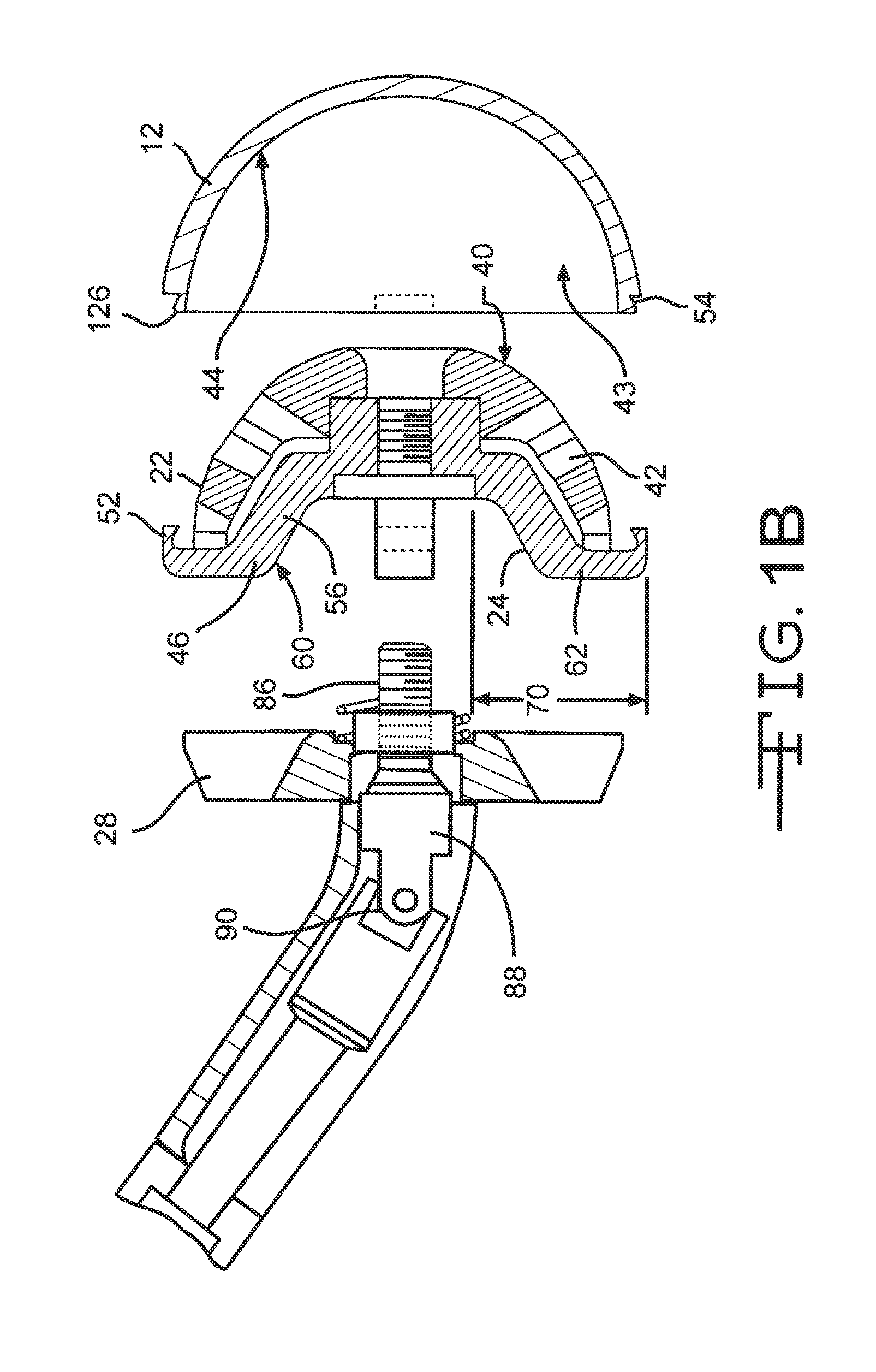
[0024]Referring now to FIGS. 1A-9, an acetabular inserter 10 is provided to aid the surgeon in controlling installation of an acetabular cup prosthesis 12. The inserter 10 has a housing 14 which encloses a drive train 16 having, at a distal end, a prosthesis engaging subassembly 18, and at the proximal end, a handle 20 which facilitates moving of the drive train by the operator. The housing 14 may be C-shaped, as shown, in order to minimize invasiveness of the surgery by better clearing anatomical structures and tissue.

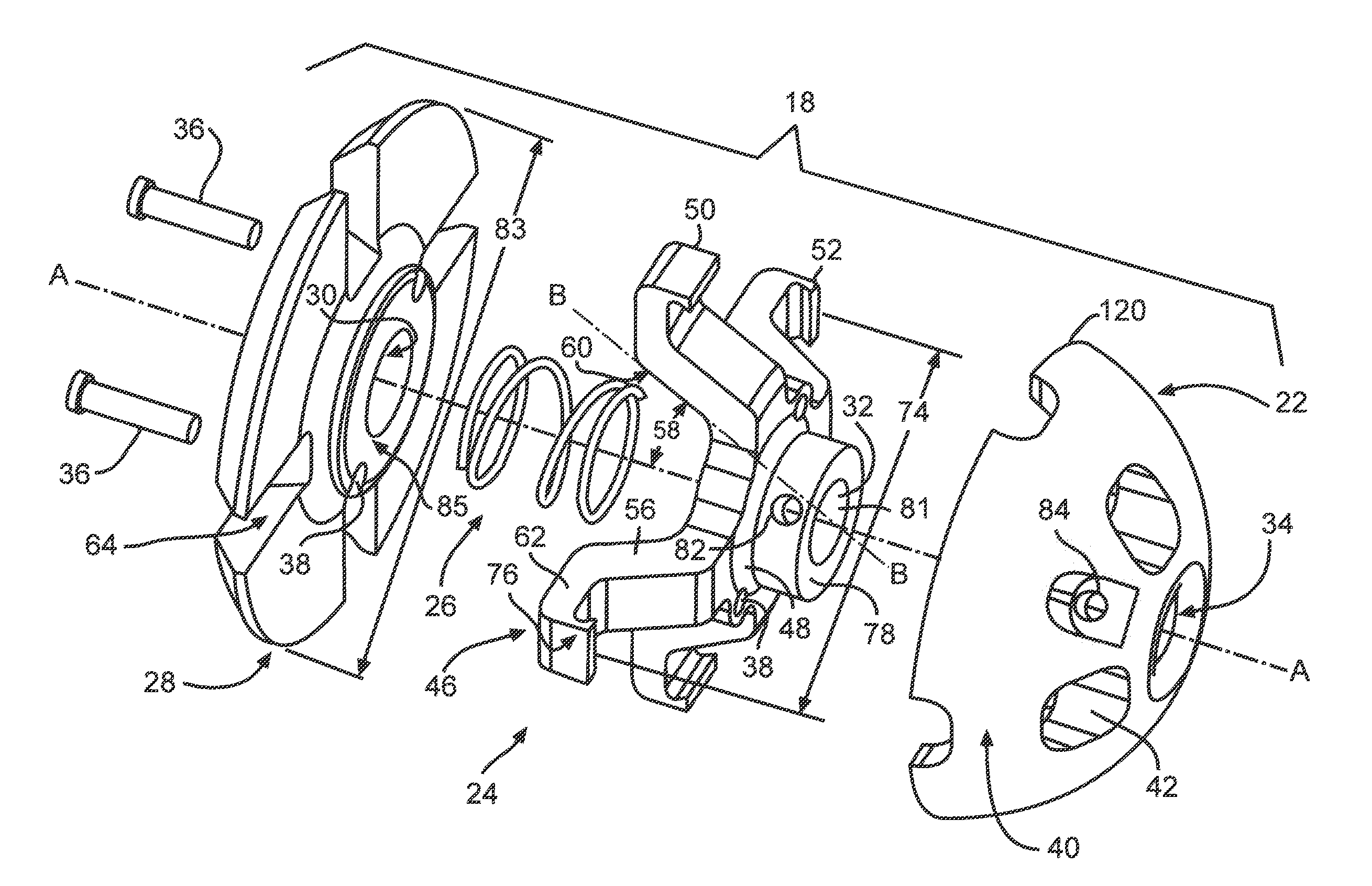
[0025]The prosthesis engaging subassembly 18, as illustrated in FIGS. 2 and 3, comprises a nose 22, a grasping plate 24, a spring 26, and an impaction plate 28 that are in direct communication with each other. The grasping plate 24 is positioned between the impaction plate 28 and the nose 22. The spring 26 is further positioned between the impaction plate 28 and the grasping plate 24 of the subassembly 18. Respective axial through-bores 30, 32, 34 extend parallel lon...


PUM


Abstract

An orthopaedic prosthetic inserter used for the implantation of double mobility cup implants is described. The inserter consists of a drive train, a C-shaped housing, and a prosthetic cup engaging subassembly. The subassembly comprises an impaction plate, a grasping plate and a domed nose. When activated by the drive train, a plurality of hook ends extending from the grasping plate latch onto the cup of the prosthetic to hold and manipulate the prosthetic cup during implantation.

Description

CROSS REFERENCE TO RELATED APPLICATIONS[0001]This application claims priority to U.S. provisional application Ser. No. 61 / 377,701, filed on Aug. 27, 2010.FIELD OF THE INVENTION[0002]This invention relates to surgical inserters for aiding in installing orthopedic prostheses, and more specifically, to an improved grasping mechanism for installing acetabular implants in the acetabular socket.BACKGROUND OF THE INVENTION[0003]A double mobility prosthetic cup is a type of acetabular implant that is designed to increase a patient's range of hip mobility. Unlike other types of acetabular implants, double mobility prosthetic cups do not have an opening through the cup portion which allows for easy manipulation during implantation. For example, a rod is typically threaded through the cup opening to the apex of the cup dome where there is typically a threaded hole. This rod is used like a handle with which to control and guide the implant during implantation. Double mobility implants, on the o...

Claims


Application Information

Patent Timeline
Patent Type & Authority Patents(United States)
IPC IPC(8): A61F2/34A61F2/46A61F2/30A61F2/32
CPCA61F2/4609A61F2002/30426A61F2002/305A61F2002/30565A61F2002/3208
Inventor BURGI, JONAS
Owner VIANT AS&O HLDG LLC
Learn More