Reflective mask blank for EUV lithography and process for producing the same
a technology of euv lithography and reflector, which is applied in the direction of photomechanical equipment, originals for photomechanical treatment, instruments, etc., can solve the problems of inability to use a conventional refractive optical system like photolithography, the conventional photolithography method is close to its limit the etching apparatus can be simplified, so as to reduce contamination during the etching process, the etching process is simplified, and the etching process is reduced
- Summary
- Abstract
- Description
- Claims
- Application Information
AI Technical Summary
Benefits of technology
Problems solved by technology
Method used
Image
Examples
example 1
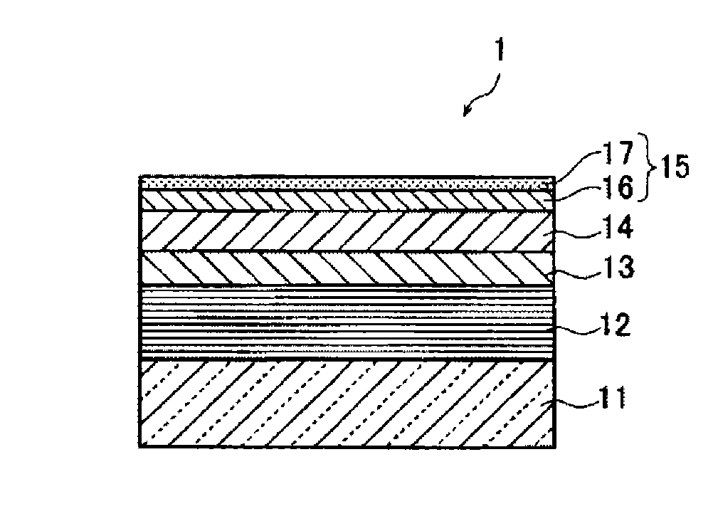
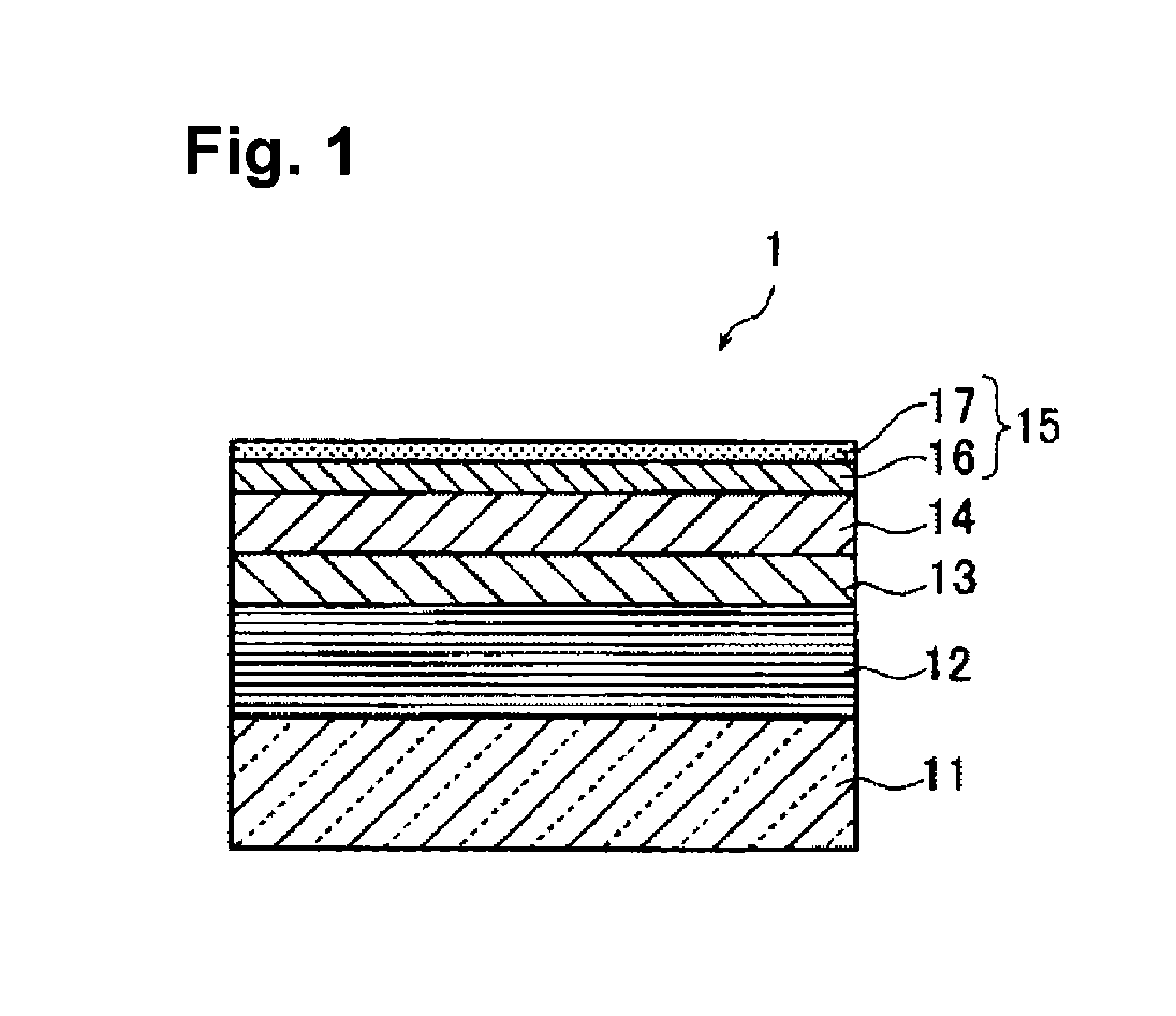
[0162]In this Example, an EUV mask blank 1 as shown in FIG. 1 was prepared.
[0163]As a substrate 11 for film formation, a SiO2—TiO2 type glass substrate (shape: about 6 inch square (length×width: about 152 mm×about 152 mm), thickness: about 6.3 mm) was used. This glass substrate has a thermal expansion coefficient of 0.2×10⁻⁷ / ° C., a Young's modulus of 67 GPa, a Poisson's ratio of 0.17 and a specific rigidity of 3.07×10⁷ m2 / s2. This glass substrate was polished to form a smooth surface having a surface roughness (rms) of at most 0.15 nm with a planarity of at most 100 nm.
[0164]On the rear surface side of the substrate 11, a Cr film having a thickness of 100 nm was formed by a magnetron sputtering method to provide a high dielectric coating having a sheet resistance of 100 Ω / □.
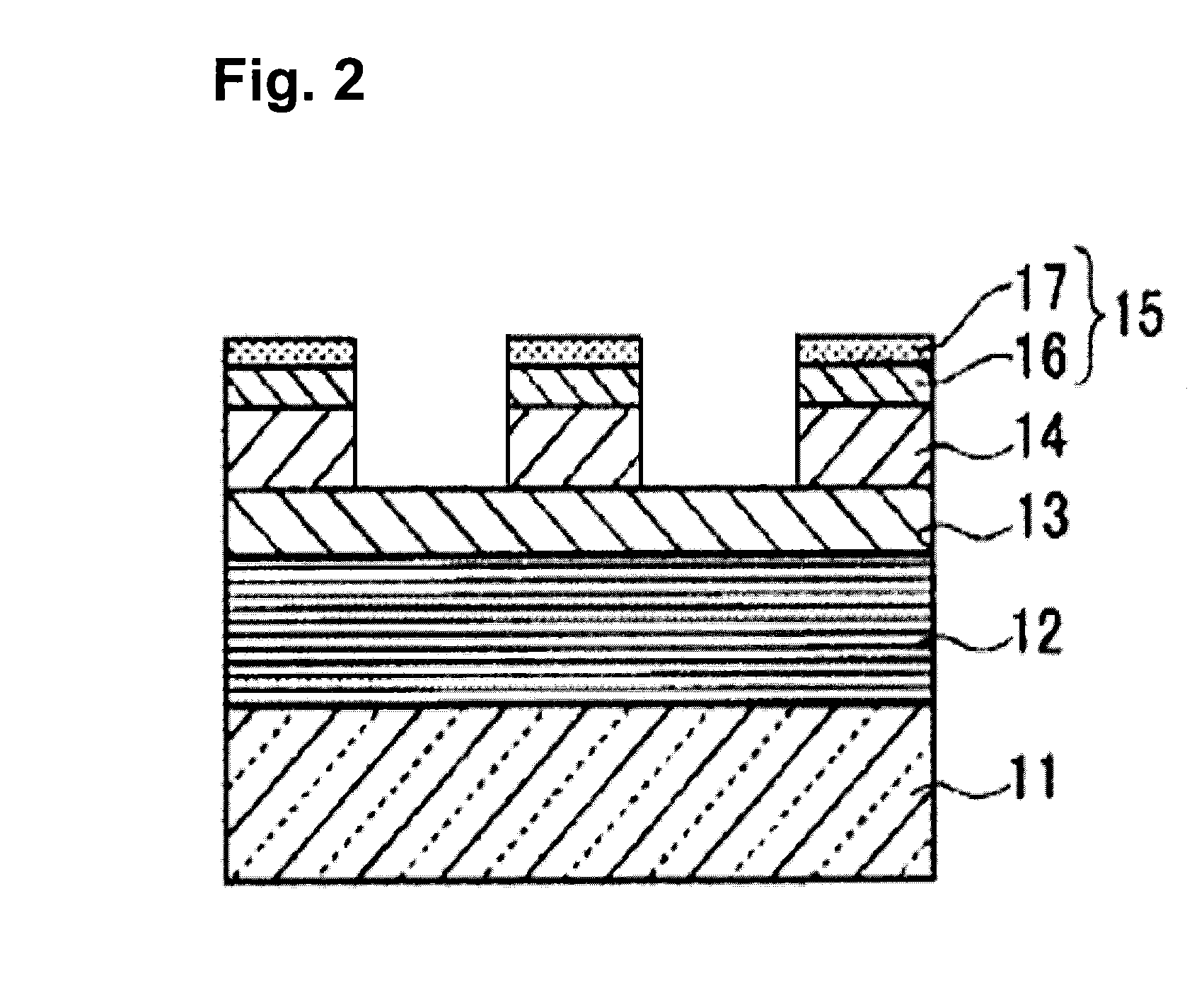
[0165]By using the formed Cr film, the substrate 11 was fixed to a usual electrostatic chuck of a flat plate shape, and on the surface of the substrate 11, a Si film and a Mo film were alternately formed by mean...
example 2
[0225]In this Example, film formation and evaluation were carried out in the same manner as in Example 1 except that a TaON film having a thickness of 3 nm was formed as the second layer 17, and the etching time was changed as shown in Table 3. Consequently, results shown in Tables 1, 2 and 4 were obtained.
example 3
[0226]In this Example, film formation and evaluation were carried out in the same manner as in Example 1 except that as the second layer 17, a TaN film having a thickness of 1 nm were formed under the same condition as the absorber layer 14, and the etching time was changed as shown in Table 3. Consequently, results shown in Tables 1, 2 and 4 were obtained.
[0227]Such obtained TaN film had a Ta content of 57 at % and a N content of 43 at %.
PUM
| Property | Measurement | Unit |
|---|---|---|
| wavelength | aaaaa | aaaaa |
| surface roughness | aaaaa | aaaaa |
| total thickness | aaaaa | aaaaa |
Abstract
Description
Claims
Application Information
 - R&D
- Intellectual Property
- Life Sciences
- Materials
- Tech Scout
- Unparalleled Data Quality
- Higher Quality Content
- 60% Fewer Hallucinations
Browse by: Latest US Patents, China's latest patents, Technical Efficacy Thesaurus, Application Domain, Technology Topic, Popular Technical Reports.
© 2025 PatSnap. All rights reserved.Legal|Privacy policy|Modern Slavery Act Transparency Statement|Sitemap|About US| Contact US: help@patsnap.com


