
Apparatus and methodology to carry out biochemical testing on a centrifugal platform using flow splitting technique

a centrifugal platform and flow splitting technology, applied in the direction of positive displacement liquid engines, laboratory glassware, instruments, etc., can solve the problems of wasting time but manpower, affecting the quality of biochemical testing, and consuming a lot of time to complete the whole procedure, so as to avoid contamination between the reagents, high rotational speed, and the characteristic of obstructing the liquid can be regained

Active Publication Date: 2015-02-03
ZHEJIANG PUSHKANG BIOTECHNOLOGY CO LTD
View PDF4 Cites 3 Cited by
  • Summary
  • Abstract
  • Description
  • Claims
  • Application Information

AI Technical Summary

Benefits of technology

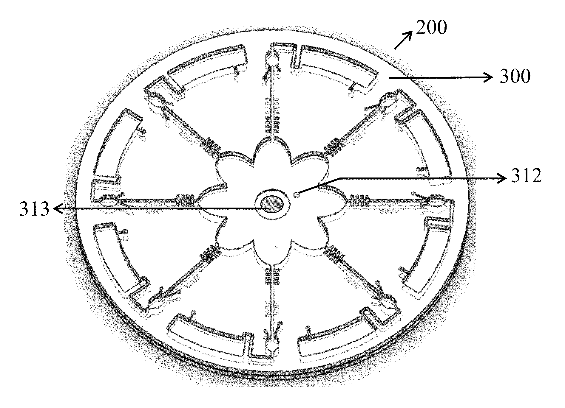
[0013]The present invention proposes an apparatus using flow splitting technique to carry out biochemical tests, also called disc flow splitting test system for solving the problems stated in the related prior arts. The present invention provides a function of controlling the flow splitting via the design of structures symmetrical to the center to prevent the interference from the Coriolis force in θ direction. On the contrary, with the present invention, the Coriolis force may help the liquid to split into a splitting chamber. Furthermore, the design of the present invention is parallel splitting and utilizes centrifugal force instead of capillary force to drive the liquid, which can hasten the liquid to be split into the splitting chambers simultaneously and reduce irregular flow. Consequently, the present invention not only possesses the advantages of the conventional CD_ELISA but greatly decreases the reagent injection times. The liquid in the present invention can be reagents used in the tests, sample, washing liquid, or the combination thereof.
[0020]To preclude the problem of microvalves being broken through at the same time caused by the former designs mentioned in the related prior arts, the present invention utilizes the splitting chamber in coordination with variant rotational speed to produce an inertial force of θ direction making the liquid split to each splitting chamber and a centrifugal force of r direction making the surface of the liquid stable and smooth. Meanwhile, if the flow-resistant element works as the microvalve, it can block the liquid. Because the distance from each microvalve to the center of the layer of the microfluidic structures is the same, the burst rotational speed of each microvalve is equal. Hence, it simply needs low rotational speed to split the reagents to each splitting chamber, then uses high rotational speed so that the reagents may burst the microvalve and flow to the detection chamber. At high rotational speed, the liquid on the surface of each microvalve could be removed so as to restore the obstructing function. Afterwards, other reagents can be loaded when necessary, and then repeat the step of bursting the microvalve. The advantages of the present invention are loading one reagent at a time to avoid the incorrectness of the releasing sequence, reducing the times of injection and easier to control the rotational speed.
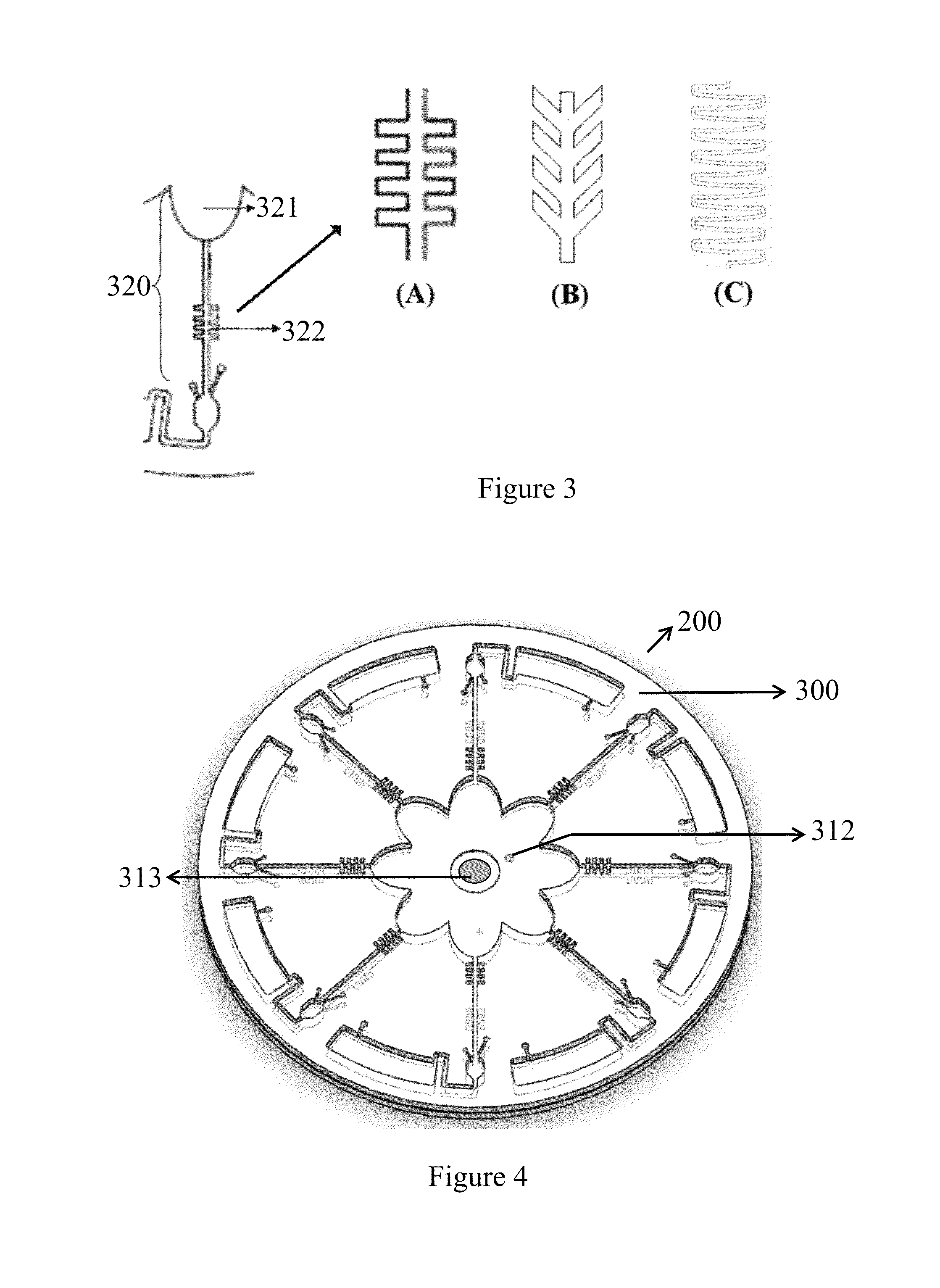
[0023]If the flow-resistant element works as the microvalve, the change of geometric shape or increase of the hydrophobicity on the surface help to obstruct the liquid proceeding with low rotational speed. The designed shape of the microvalve comprises a round shape or a fish-bone shape. If the reagents comprise protein, the protein could stick to the wall of the microvalve with the round shape causing dysfunction. When the reagents flow the fish-bone shape microvalve, the reagents could easily remain in the microvalve causing the contamination between the reagents. Therefore, in the present invention, the angle of the fish-bone shape microvalve has been adjusted slightly, becoming the herringbone shape. The adjustment not only keeps the feature of the microvalve obstructing the liquid but avoiding the liquid remaining in the microvalve. This resolves the problem of the contamination between the reagents.
[0027]The present invention does not confine to the double sides and double layers. If there are many kinds of reagents in the experiment, there could be double sides with three layers, four layers and even more. If the microvalve works as the flow-resistant element, comparing to the single side and single layer, the design of multiple layers can avoid the different reagents flowing through the same microvalve due to the injection into the different injection chambers in different layers. The problem of the dysfunctional microvalve which cannot obstruct the liquid due to the reagents comprising protein or surfactants flowing through the microvalve can be avoided. The contamination between the reagents can also be avoided. If the multiple layers are not adopted, after the microvalve is broken through, then we need the rotation of the rotator platform with a high rotational speed persists for certain time, for instance, 10 minutes, to dry up the microvalve, so the characteristic of obstructing the liquid can be regained.

Problems solved by technology

Because each step requires an incubation time and washing process, the overall sandwich ELISA often takes much time, even days, to accomplish the whole procedures.
The conventional procedure using 96-wells microtiter plate must manually and repeatedly load the samples into the wells which not only wastes time but manpower.
Such design not merely simplifies the procedures but diminishes the volume of reagents required and broadens the reaction surface area.
However, in the execution of CD_ELISA, there are still some problems that need to be overcome.
It is learned from references that for the sake of breaking through the microfluidic valves, each (burst) rotational speed, from the outer part of the microfluidic disc to the inner part, has to reach 327, 546, 968, 1180 and 1506 revolutions per minute (RPM) individually; nevertheless, due to the shape of the disc, there is no way to speed up the (burst) rotational speed to enlarge the gap.
If the gap of the (burst) rotational speed between each microfluidic valve is not big enough, the range of each speed may overlap resulting in bursting more than one microfluidic valves at the same time under the same rotational speed, and this situation will lead the test to fail.
Though the method can properly control when to burst the valves to avoid releasing the liquid in wrong order, it becomes more difficult to make the disc, in addition, a sophisticated machine is needed to perform the task, hence the cost of entire tests increases.
Without considering the huge cost, even if the ferrowax microvalves has solved the problem of unstable (burst) rotational speed of the microfluidic valve, during the test, a large quantity of liquid to be injected are still required.
Suppose there are 12 sets of microfluidic channels on a microfluidic disc and 5 reservoirs within each set of the microfluidic channels, the reagents require to be injected in for 60 times. Again, it takes lots of time and manpower along with the volatilization problem.
Thus it is sure time and labor consuming, and the man-made negligence error would be likely to rise.
In this manner, however, the liquid fills in sequence, and therefore takes longer time to split; moreover, the capillary force is easily unstable while filling up the splitting chambers, prone to failure of splitting.
Lee et al. in 2009 proposed combining CD_ELISA and the crotched flow channels; however, while the liquid splits, such design may easily be affected by the Coriolis force produced from the rotation of the disc, which makes the flow opposite to the direction of the flow channel as the disc rotates larger and causes the allocation of the liquid uneven.
Once more, the problem has remained unsolved.

Method used


Image

  • Apparatus and methodology to carry out biochemical testing on a centrifugal platform using flow splitting technique
  • Apparatus and methodology to carry out biochemical testing on a centrifugal platform using flow splitting technique
  • Apparatus and methodology to carry out biochemical testing on a centrifugal platform using flow splitting technique

Examples


Embodiment Construction

[0036]The present convention is in accordance with embodiments, trying to solve the disadvantages of prior arts.

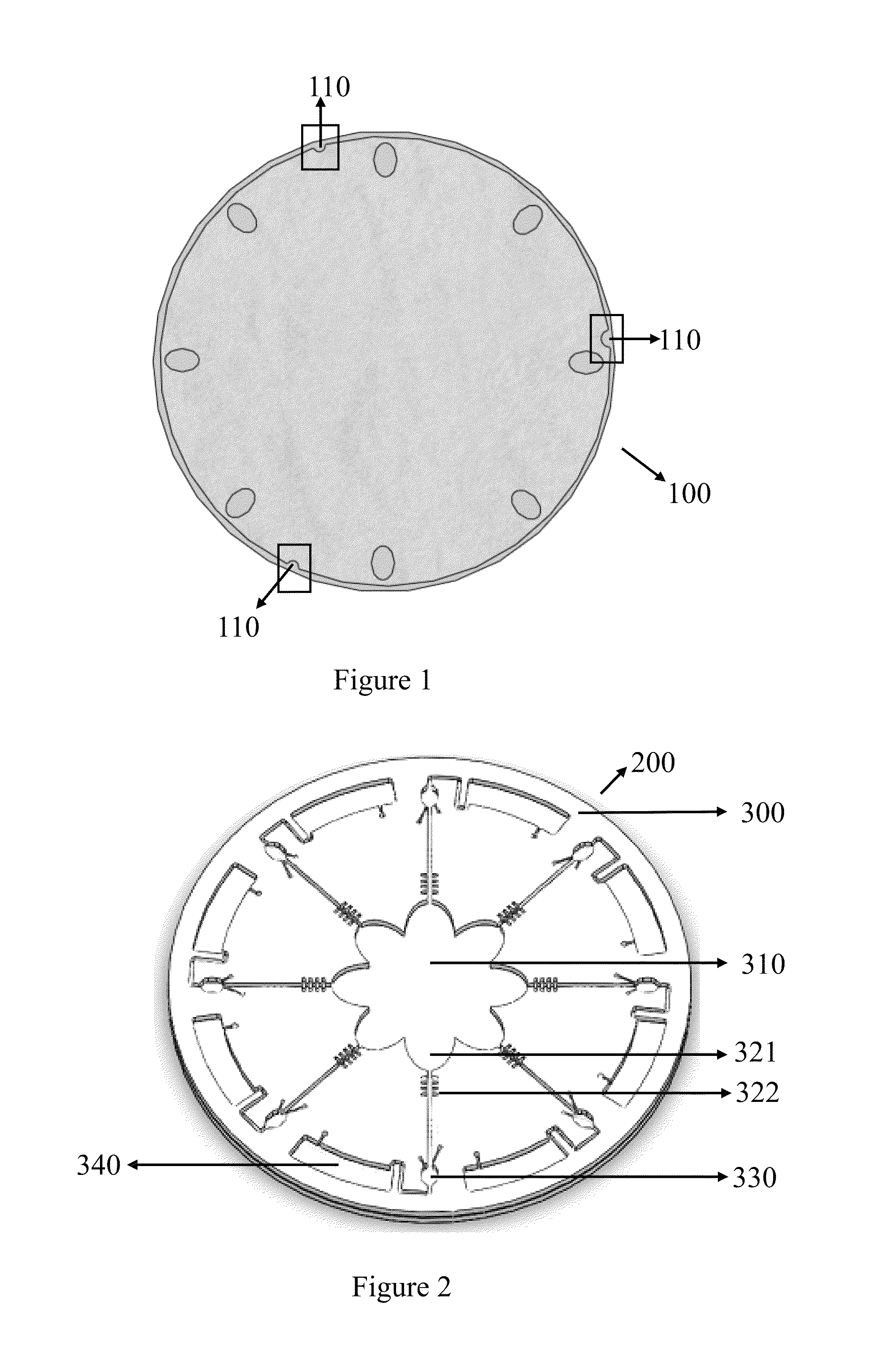
[0037]FIG. 1 is one of the embodiments to demonstrate a rotator platform 100. The rotator platform 100 comprises at least one device on the rotator platform corresponding to at least one notch 110. By the at least one notch 110, a microfluidic disc 200 is fixed on the rotator platform 100.

[0038]In the FIG. 2, the microfluidic disc 200 comprises a layer of microfluidic structures 300. From the center to the periphery of the layer of the microfluidic structures 300 comprising: an injection chamber 310, a splitting chamber 321, a flow-resistant element 322, at least one detection chamber 330, and at least one waste chamber 340.

[0039]At least one microfluidic channel 320 comprises the splitting chamber 321 and the flow-resistant element 322. The flow-resistant element 322 has choices of microvalve with round shape or fish-bone shape the as shown in FIG. 3A. If reagents compris...


PUM

PropertyMeasurementUnit
timeaaaaaaaaaa
frequencyaaaaaaaaaa
volumeaaaaaaaaaa

Abstract

The invention provides an apparatus and methodology to carry out biochemical testing on a centrifugal platform using flow splitting technique. In conventional biochemical testing, reagents need to be loaded individually into each reservoir. By using the flow splitting technique in this invention, one reagent only need to be loaded once, then, it can be evenly distributed into each reaction chambers in single or multiple layers format. The invention greatly reduces the required manpower when large numbers of assays are integrated on one platform. Because of the invention, many medical examinations can be performed efficiently, thus reduce the waste of manpower, time and cost.

Description

BACKGROUND OF THE INVENTION[0001]1. Field of the Invention[0002]This present invention relates to a rapid test apparatus, more particularly to the rapid test apparatus in which the procedure comprising several times of injection of the same type reagent or injection of various types of reagents.[0003]2. Description of Related Art[0004]Take the sandwich ELISA for example. Capture antibody, antigen, detection antibody labeled with HRP, and chromogen solution are required to be loaded in sequence in this experiment. Because each step requires an incubation time and washing process, the overall sandwich ELISA often takes much time, even days, to accomplish the whole procedures. The conventional procedure using 96-wells microtiter plate must manually and repeatedly load the samples into the wells which not only wastes time but manpower.[0005]In order to solve the problems stated above, Lee et al., in 2001, proposed microfluidic disc platform ELISA, abbreviated “CD-ELISA.” According to th...

Claims


Application Information

Patent Timeline
Patent Type & Authority Patents(United States)
IPC IPC(8): B01L3/00G01N33/53
CPCG01N33/5302B01L3/502738B01L3/502746B01L2200/0605B01L2300/0803B01L2300/0864B01L2300/0883B01L2400/0409B01L2400/0688B01L2400/086Y10T436/111666G01N33/53G01N35/08
Inventor SHIH, CHIH-HSINWU, HO-CHINYANG, YU-PING
Owner ZHEJIANG PUSHKANG BIOTECHNOLOGY CO LTD
Learn More