
System and method for allocating identifier to multi-BMS

a multi-bms, identifier technology, applied in the direction of battery/fuel cell control arrangement, secondary cell servicing/maintenance, instruments, etc., can solve the problem of limiting the charge/discharge state control of all the batteries using a single bms, signal transmission failure from the faulty communication section, and the inability to recognize the charge/discharge state of the battery cell, so as to reduce maintenance and repair costs, prevent a possible overlap of identifier

Active Publication Date: 2015-01-13
LG ENERGY SOLUTION LTD
View PDF14 Cites 9 Cited by
  • Summary
  • Abstract
  • Description
  • Claims
  • Application Information

AI Technical Summary

Benefits of technology

The present invention solves the problem of being unable to allocate an identifier to a slave BMS connected after a faulty section of a serial communication network. It also eliminates the need for removing or replacing the whole communication network and slave BMS in case of an error, thus reducing maintenance and repair costs. The invention also allows for the allocation of identifiers to a multi-BMS in a sequential order, preventing identifier overlapping and improving installation for a BMS and battery pack reliability. There is also the advantage of being free to arrange the placement of the master and slave BMS in a battery pack without the need for a foremost or backmost end of a serial communication network.

Problems solved by technology

Because the battery pack of the multi-module structure includes a plurality of batteries, there is a limitation in controlling the charge / discharge state of all the batteries using a single BMS.
Accordingly, when an error or a disconnection occurs in a certain section of the serial communication network, signal transmission fails from the faulty communication section.
In this case, the master BMS cannot communicate with a slave BMS having no allocated identifier, and thus, cannot recognize the charge / discharge state of a battery cell or a battery module included in the slave BMS having no allocated identifier.

Method used


Image

  • System and method for allocating identifier to multi-BMS
  • System and method for allocating identifier to multi-BMS
  • System and method for allocating identifier to multi-BMS

Examples


Embodiment Construction

[0042]Hereinafter, preferred embodiments of the present disclosure will be described in detail with reference to the accompanying drawings. Prior to the description, it should be understood that the terms used in the specification and the appended claims should not be construed as limited to general and dictionary meanings, but interpreted based on the meanings and concepts corresponding to technical aspects of the present disclosure on the basis of the principle that the inventor is allowed to define terms appropriately for the best explanation. Therefore, the description proposed herein is just a preferable example for the purpose of illustrations only, not intended to limit the scope of the disclosure, so it should be understood that other equivalents and modifications could be made thereto without departing from the spirit and scope of the disclosure.

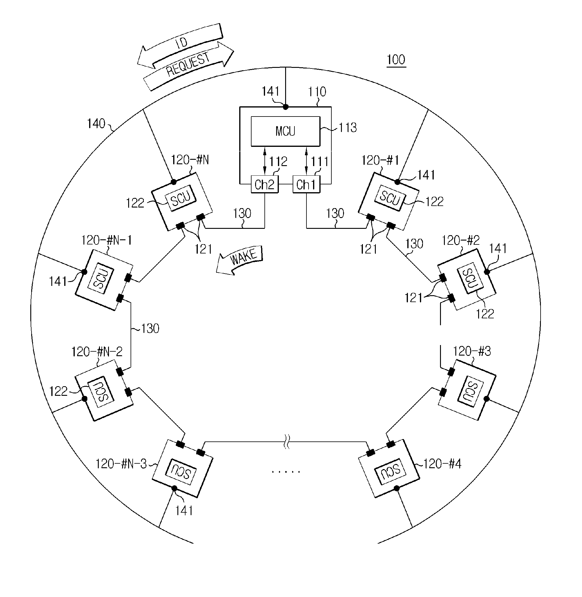
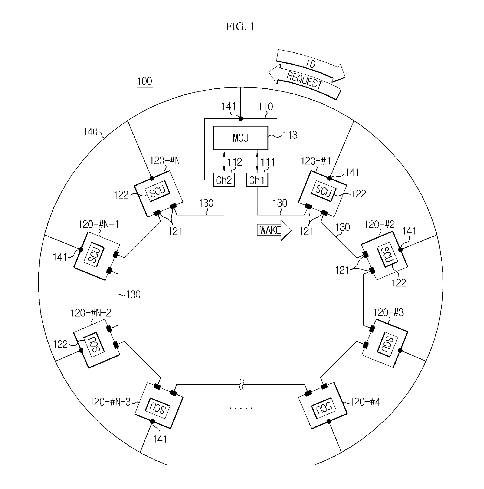
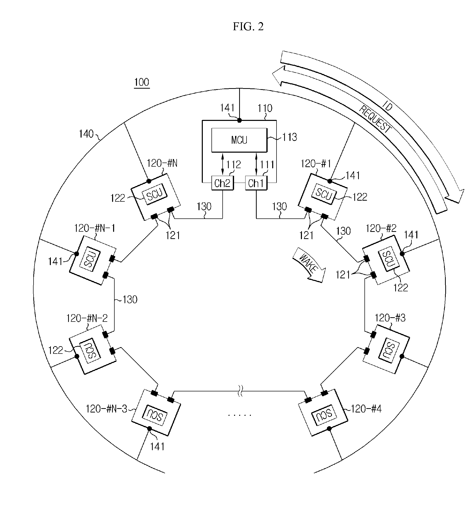
[0043]FIG. 1 is a schematic block diagram illustrating a configuration of a system 100 for allocating an identifier to a multi-BMS...


PUM

PropertyMeasurementUnit
charge/discharge capacityaaaaaaaaaa
period of timeaaaaaaaaaa
poweraaaaaaaaaa

Abstract

Disclosed is a multi-BMS identifier allocation system. The multi-BMS identifier allocation system according to the present invention comprises a master BMS and N slave BMSs (N is an integer greater than or equal to 2) which are connected to a series communication network and a parallel communication network, wherein the master BMS comprises at least two first and second master communication channels which form a communication interface with the series communication network and selectively output a forward or backward enabling signal and allocates unique communication identifiers to the slave BMSs through the parallel communication network, and the first to Nth slave BMSs start enabling in response to the forward or backward enabling signal received through the series communication network, are allocated the identifiers from the master BMS through the parallel communication network, and output an enabling signal to an adjacent slave BMS along a transmission direction of the enabling signal.

Description

CROSS-REFERENCE TO RELATED APPLICATION[0001]The present application is a continuation of International Application No. PCT / KR2013 / 001334 filed on Feb. 20, 2013, which claims priority to Korean Patent Application No. 10-2012-0016829 filed in the Republic of Korea on Feb. 20, 2012, the disclosures of which are incorporated herein by reference.TECHNICAL FIELD[0002]The present disclosure relates to a system and method for allocating an identifier to each battery management system (BMS) of a battery pack having a multi-BMS structure, and more particularly, to a system and method for allocating an identifier to all slave BMSs even though an error occurs in a serial communication network.BACKGROUND ART[0003]Due to its characteristics of being easily applicable to various products and electrical characteristics such as a high energy density, a secondary battery is not only commonly applied to a portable equipment, but universally applied to an electric vehicle (EV), a hybrid vehicle (HV), o...

Claims


Application Information

Patent Timeline
Patent Type & Authority Patents(United States)
IPC IPC(8): H01M10/44H01M10/46H02J7/00H02J7/04H04Q9/00
CPCH04Q9/00H01M10/441H02J7/0068H02J7/04H04Q2209/10H04Q2209/30B60L58/12H04Q2209/883Y02E60/10Y02T10/70Y02T90/16G01R31/36H01M10/44
Inventor LEE, HYUN-CHULPARK, JONG-MINKANG, YEONG-JU
Owner LG ENERGY SOLUTION LTD
Learn More