Switch disk array, storage system and data storage path switching method
a technology of switch disk array and switch disk array, which is applied in the field of data storage technologies, can solve the problems of increasing the redundant data amount of the server and the disk array, and achieve the effect of reducing the redundant data amount of the server and the switch disk array
- Summary
- Abstract
- Description
- Claims
- Application Information
AI Technical Summary
Benefits of technology
Problems solved by technology
Method used
Image
Examples
embodiment 1
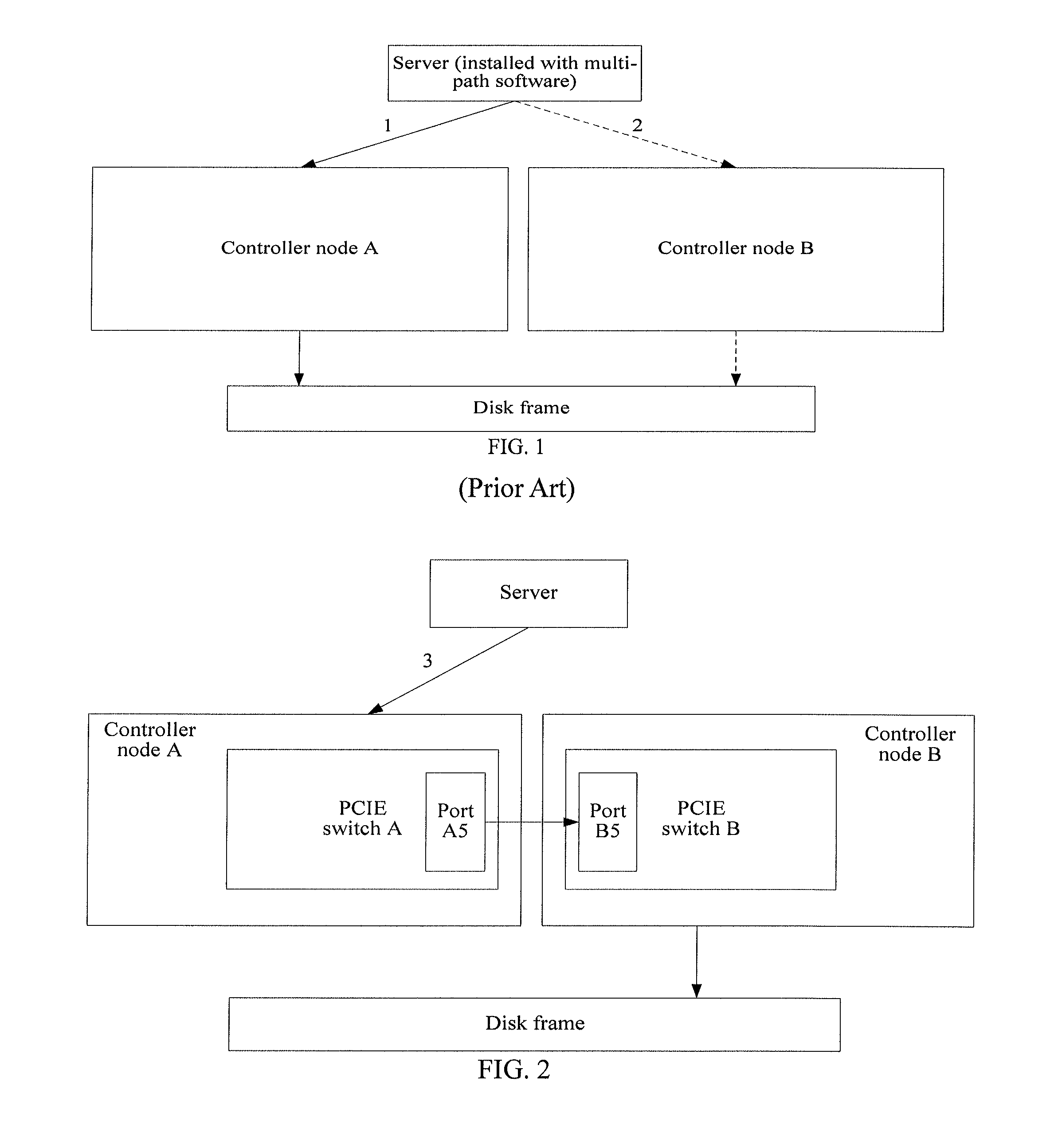
[0036]Referring to FIG. 2, a schematic structural diagram of a dual controller disk array and a schematic connection diagram of the dual controller disk array and a server according to this embodiment are shown.
[0037]The dual controller disk array includes a disk frame and two controller nodes. Each controller node includes a switch, where a port of the switch is connected to a port of a switch of a peer controller node. Each controller node receives, through a switch of a local controller node, data sent by the server, and stores the data in the disk frame.
[0038]For ease of description, two controller nodes in the dual controller disk array are referred to as a controller node A and a controller node B. Functions of the controller node A and the controller node B are similar, and the controller node A may be an active / standby controller node of the controller node B and the controller node B may be an active / standby controller node of the controller node A. The server or the disk a...
embodiment 2
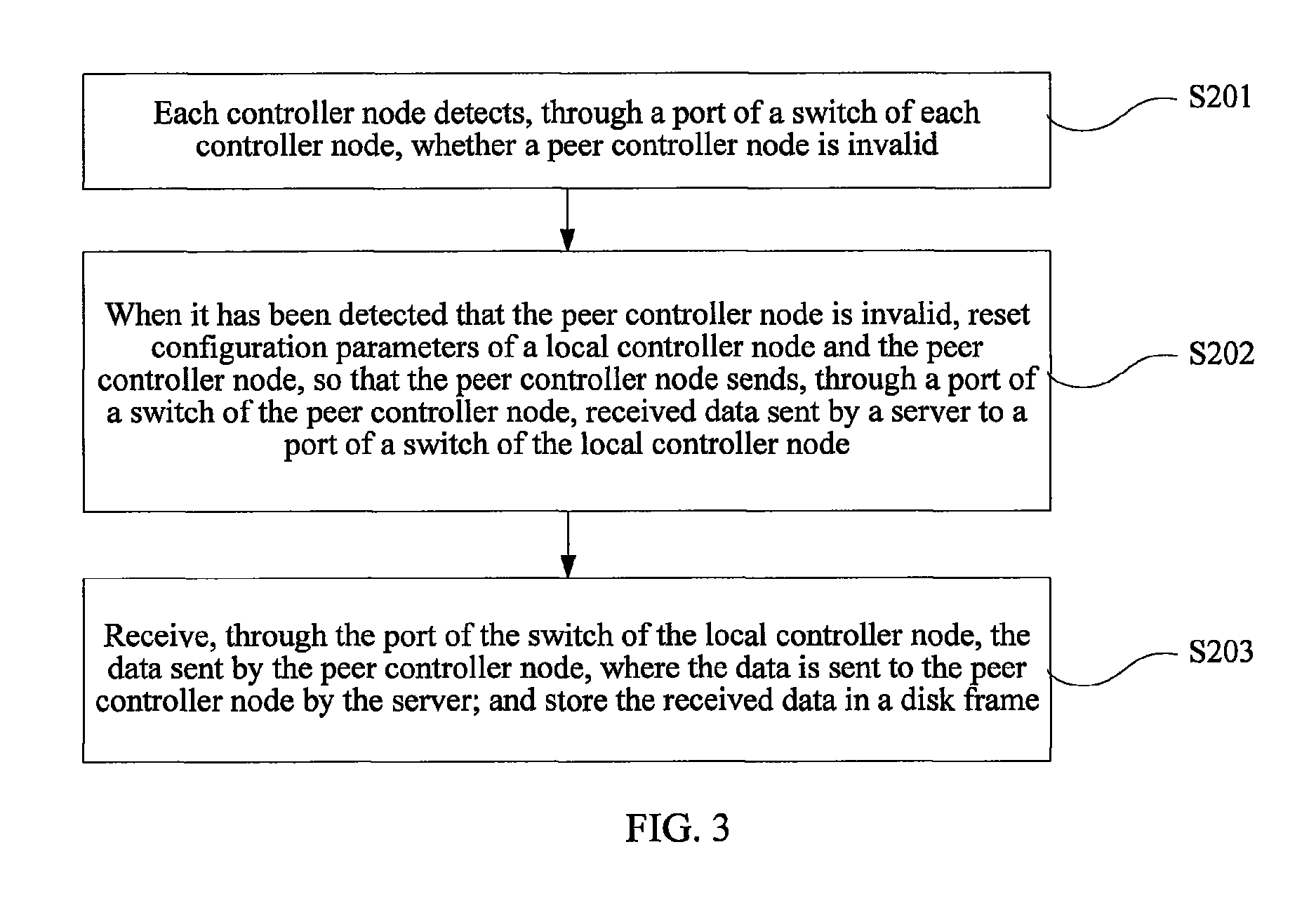
[0048]Referring to FIG. 3, this embodiment provides a data storage path switching method, and each controller node in FIG. 2 may implement data storage path switching by adopting the method.
[0049]In this embodiment, it is taken as an example that a controller node A is invalid and a controller node B takes over data on the invalid controller node A.
[0050]Step 201: Each controller node detects, through a port, which is of a switch of each controller node and connected to a peer controller node, whether the peer controller node is invalid.
[0051]The controller node B detects whether the controller node A is invalid through a port B5. A manner for detecting, by the controller node B, whether the controller node A is invalid includes, but is not limited to:
[0052]The controller node B judges whether a port B5 of a switch of a local controller node receives a handshake message sent by the controller node A in a preset time period; and if a judgment result is no, determines that the control...
embodiment 3
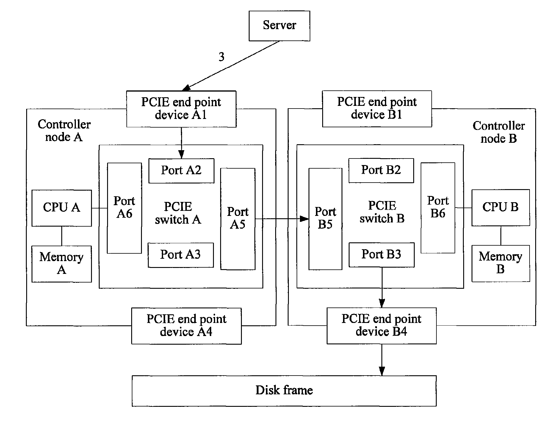
[0062]An embodiment provides a specific structure of a dual controller disk array in a scenario that both the dual controller disk array and a server support a PCIE bus, as shown in FIG. 4.
[0063]Each controller node in FIG. 4 includes a switch (a port of the switch is connected to a port of a switch of a peer controller node), and also includes a first end point device connected to the server, a second end point device connected to a disk frame, and a central processing unit CPU configured to run a read or write control program.
[0064]Optionally, the first end point device and the second end point device may be a PCIE end point device, and the switch may be a PCIE switch. Specifically, a controller node A has a PCIE end point device A1 connected to the server, and a PCIE end point device A4 connected to the disk frame. The controller node A also has a PCIE switch A, a CPU A configured to run the read or write control program, and a memory A. The PCIE switch A has multiple ports, whic...
PUM
 Abstract
Description
Claims
Application Information
 - R&D
- Intellectual Property
- Life Sciences
- Materials
- Tech Scout
- Unparalleled Data Quality
- Higher Quality Content
- 60% Fewer Hallucinations
Browse by: Latest US Patents, China's latest patents, Technical Efficacy Thesaurus, Application Domain, Technology Topic, Popular Technical Reports.
© 2025 PatSnap. All rights reserved.Legal|Privacy policy|Modern Slavery Act Transparency Statement|Sitemap|About US| Contact US: help@patsnap.com


