
Method and system for improving energy efficiency in an HVAC system

a technology for hvac systems and energy efficiency, applied in the field of building systems, can solve problems such as waste of energy and excess amount of outside air, and achieve the effect of improving energy efficiency

Active Publication Date: 2015-01-06
SIEMENS IND INC
View PDF31 Cites 34 Cited by
  • Summary
  • Abstract
  • Description
  • Claims
  • Application Information

AI Technical Summary

Benefits of technology

[0005]This disclosure describes a method and system for improving energy efficiency in a heating, ventilation, and air conditioning (HVAC) system.
[0006]In accordance with one embodiment of the disclosure, a method is performed by a zone controller for a zone of a building to improve energy efficiency in an HVAC system. The method includes operating in a ventilation mode. A temperature of the zone and outside air conditions for the building are monitored. A determination is made regarding whether to switch from the ventilation mode to an economizing mode based on a first set point for the temperature of the zone and based on the outside air conditions. The first set point is determined based on a second set point for the temperature that is different from the first set point. A determination is made regarding whether to activate the HVAC system based on the second set point.

Problems solved by technology

As buildings are rarely fully occupied, the HVAC system wastes energy heating, cooling, and dehumidifying this excess amount of outside air.
In many applications, the HVAC fan is programmed to run 24 / 7, regardless of heating or cooling need, or occupancy levels, further wasting energy.

Method used


Image

  • Method and system for improving energy efficiency in an HVAC system
  • Method and system for improving energy efficiency in an HVAC system
  • Method and system for improving energy efficiency in an HVAC system

Examples


Embodiment Construction

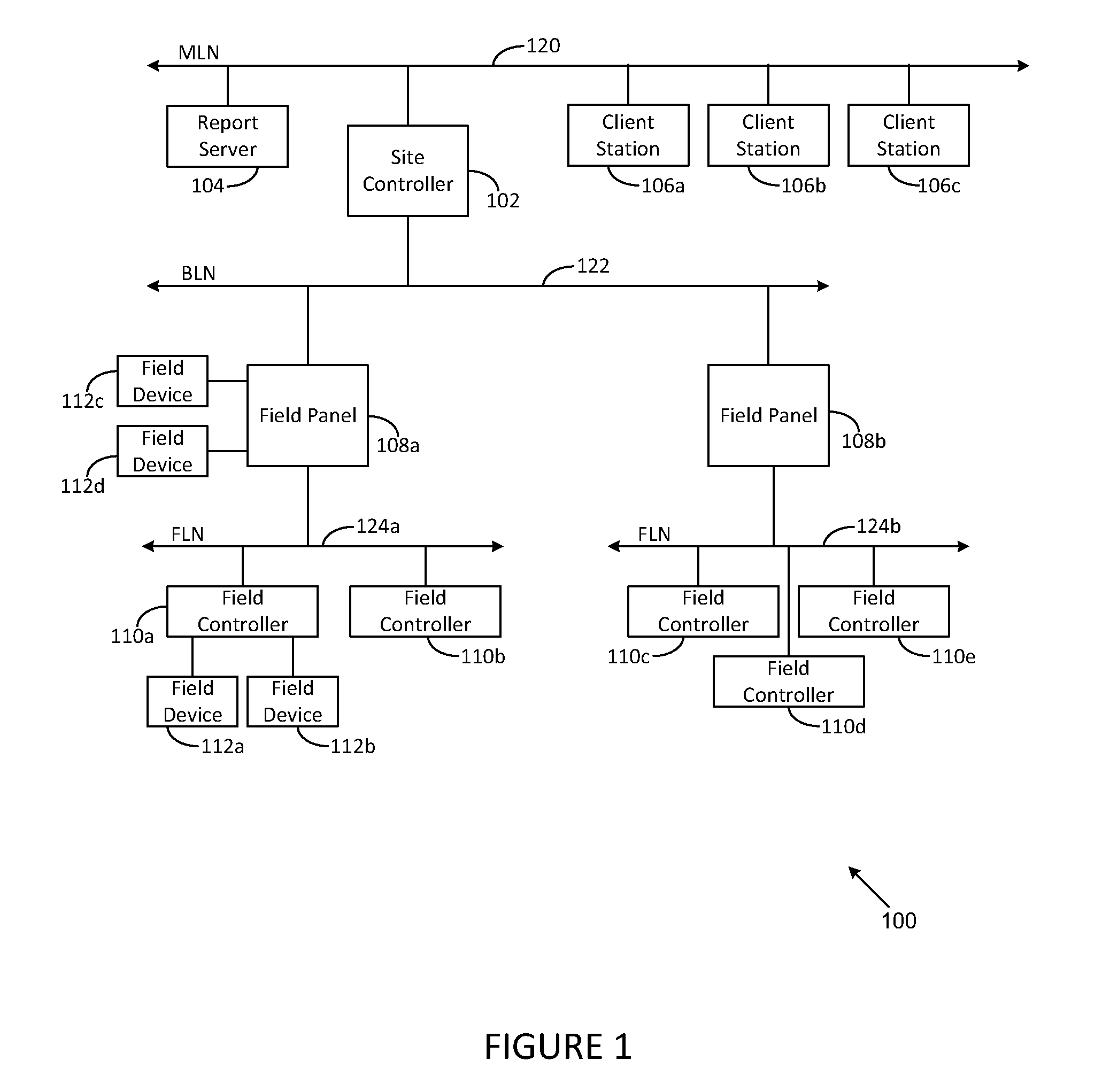
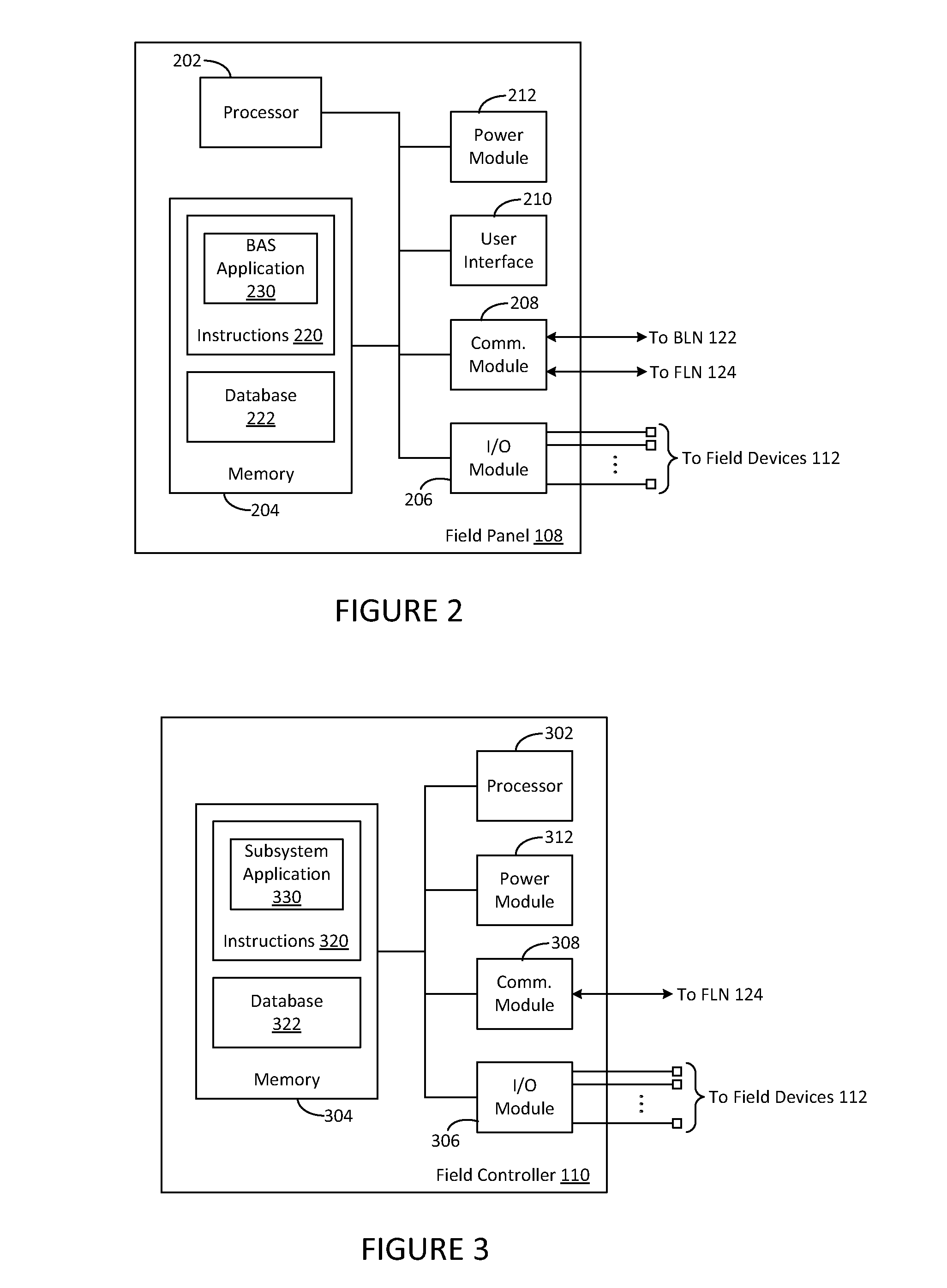
[0017]FIGS. 1 through 5, discussed below, and the various embodiments used to describe the principles of the present disclosure in this patent document are by way of illustration only and should not be construed in any way to limit the scope of the disclosure. Those skilled in the art will understand that the principles of the present disclosure may be implemented in any suitably arranged device or system.

[0018]Demand Control Ventilation (DCV) systems vary the amount of outside air supplied into a commercial building based on occupancy. Older heating, ventilation and air conditioning (HVAC) systems require an expensive damper retrofit, or total unit replacement in order to support conventional DCV. Recently, intelligent DCV (IDCV) has been developed to allow both new and legacy HVAC systems in real-time to adjust the amount of outside air based on actual occupancy levels, to improve air quality in humid climates, and to eliminate wasted fan energy. This IDCV provides significant ann...


PUM


Abstract

A method performed by a zone controller for a zone of a building for improving energy efficiency in a heating, ventilation, and air conditioning (HVAC) system is provided. The method includes operating in a ventilation mode. A temperature of the zone and outside air conditions for the building are monitored. A determination is made regarding whether to switch from the ventilation mode to an economizing mode based on a first set point for the temperature of the zone and based on the outside air conditions. The first set point is determined based on a second set point for the temperature that is different from the first set point. A determination is made regarding whether to activate the HVAC system based on the second set point.

Description

TECHNICAL FIELD[0001]The present disclosure is directed, in general, to building systems and, more particularly, to a method and system for improving energy efficiency in a heating, ventilation, and air conditioning (HVAC) system.BACKGROUND OF THE DISCLOSURE[0002]Building automation systems encompass a wide variety of systems that aid in the monitoring and control of various aspects of building operation. Building automation systems include security systems, fire safety systems, lighting systems, and HVAC systems. The elements of a building automation system are widely dispersed throughout a facility. For example, an HVAC system may include temperature sensors and ventilation damper controls, as well as other elements, that are located in virtually every area of a facility. These building automation systems typically have one or more centralized control stations from which system data may be monitored and various aspects of system operation may be controlled and / or monitored.[0003]T...

Claims


Application Information

Patent Timeline
Patent Type & Authority Patents(United States)
IPC IPC(8): G05B21/00G01M1/38F24F13/06F24F11/02F24F7/007F24F7/06F25B29/00F24F3/00G05D23/00G05B15/00G05B13/00F24F13/10F24F11/00
CPCF24F11/0001F24F11/006F24F2011/0006F24F2011/0064F24F11/30F24F11/62F24F11/65F24F11/56F24F11/58F24F11/46F24F11/70
Inventor BESTER, COLINBARTMESS, ROBERT
Owner SIEMENS IND INC
Learn More