
System and method for controlling movement of vehicles

a technology for controlling the movement of vehicles and vehicles, applied in the field of vehicle operations, can solve the problems of not necessarily maximizing the efficiency of fuel consumption, and achieve the effects of reducing the amount of fuel consumed, reducing emissions, and reducing the amount of emissions

Active Publication Date: 2014-12-30
GE GLOBAL SOURCING LLC
View PDF348 Cites 52 Cited by
  • Summary
  • Abstract
  • Description
  • Claims
  • Application Information

AI Technical Summary

Benefits of technology

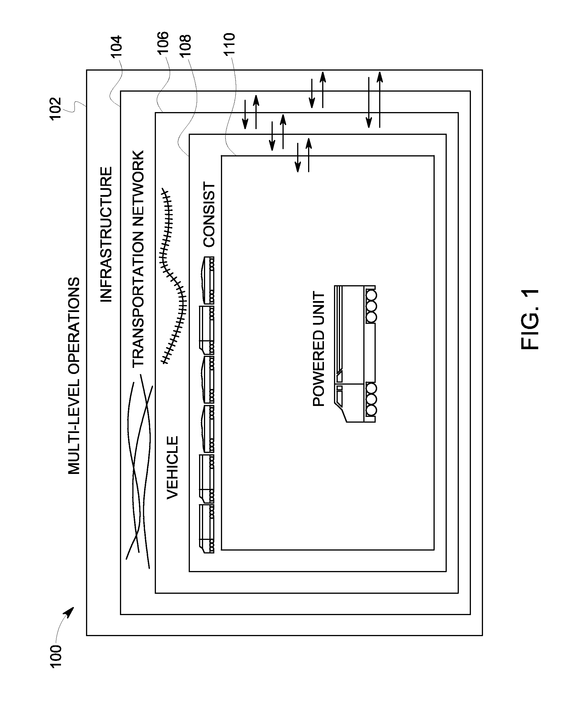
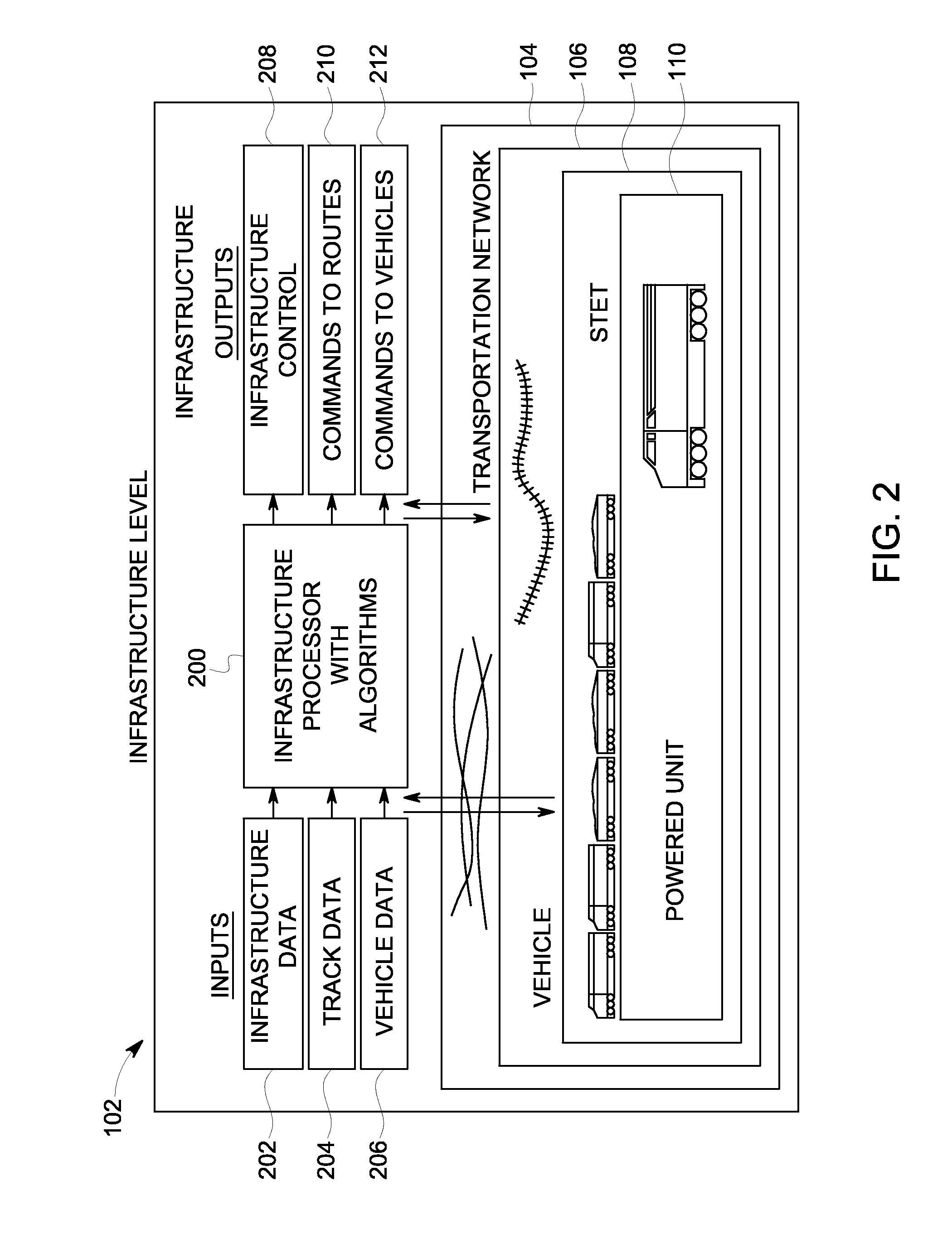
[0014]Another aspect of the presently described subject matter is the provision of a method and system for multi-level railway operations improvement for a railroad system that identifies operating constraints and data at one or more levels, communicates these constraints and data to other levels (e.g., adjacent levels) and improves performance at one or more of the levels based on the data and constraints of the other levels relative to performance of the one or more levels without communication of the constraints and data.
[0016]Aspects of the presently described subject matter may further include improving performance at a railroad infrastructure level, railway track network level, individual rail vehicle level within the network, consist level within the rail vehicle, and the individual powered unit (e.g., locomotive) level within the consist.
[0018]Aspects of the presently described subject matter may include optimizing (e.g., improving) performance of the various levels in light of business objective functions of an operating company, such as on-time deliveries, asset utilization, minimum or reduced fuel usage, reduced emissions, optimized or reduced crew costs, reduced dwell time, reduced maintenance time and costs, and / or reduced overall system costs.
[0019]These aspects of the presently described subject matter may provide benefits such as reduced journey-to-journey fuel usage variability, fuel savings for powered units (e.g., locomotives) operating within the system, graceful recovery of the system from upsets (e.g., mechanical failures), elimination or reduction of out-of-fuel mission failures, improved fuel inventory handling logistics, and / or decreased autonomy of crews in driving decisions.
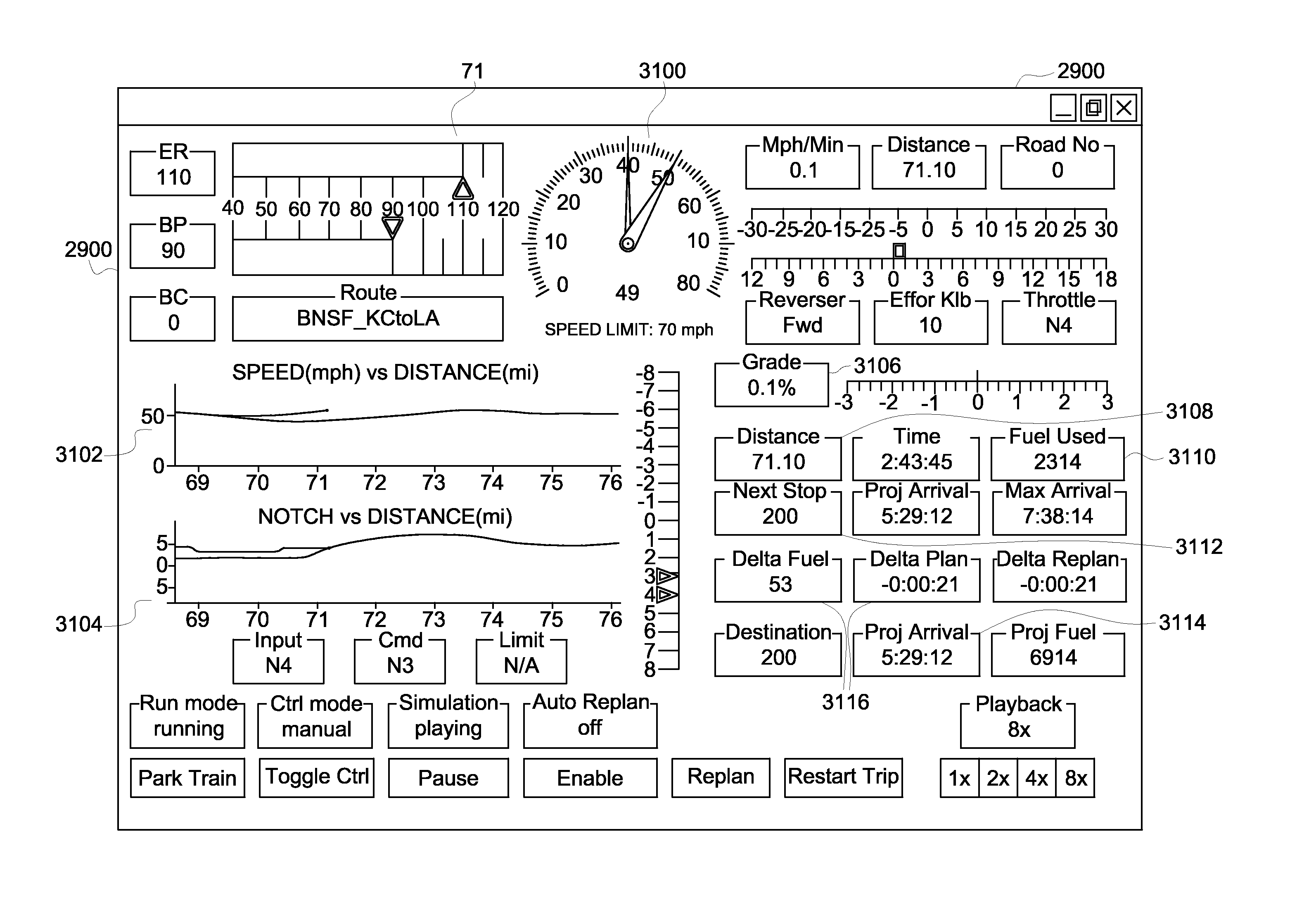
[0026]In another embodiment, a system includes a trip planner device and a converter device. The trip planner device is configured to obtain a trip plan that designates operational settings for a vehicle during a trip along one or more routes. The trip plan designates the operational settings to reduce at least one of fuel consumed or emissions generated by the vehicle during the trip relative to the vehicle traveling over the trip according to at least one other plan. The converter device is configured to generate one or more first control signals for directing operations of the vehicle according to the operational settings designated by the trip plan and to obtain actual operational parameters of the vehicle for comparison to the operational settings designated by the trip plan. The converter device also is configured to generate one or more corrective signals for directing operations of the vehicle in order to reduce one or more differences between the actual operational parameters and the operational settings designated by the trip plan.

Problems solved by technology

Rather, optimizing the fuel efficiency may mean that the fuel efficiency is increased, but not necessarily maximized.
As another example, optimizing emission generation may not mean completely eliminating the generation of all emissions.

Method used


Image

  • System and method for controlling movement of vehicles
  • System and method for controlling movement of vehicles
  • System and method for controlling movement of vehicles

Examples


Embodiment Construction

[0065]Reference will now be made in detail to the embodiments consistent with the invention, examples of which are illustrated in the accompanying drawings. Wherever possible, the same reference numerals used throughout the drawings refer to the same or like parts.

[0066]Though example embodiments of the presently described inventive subject matter are set forth with respect to rail vehicles, specifically trains and locomotives having diesel engines, one or more embodiments of the inventive subject matter may be applicable for other uses, such as but not limited to off-highway vehicles (OHV), automobiles, marine vessels, and / or stationary units, each which may use an engine, such as a diesel engine. Toward this end, when discussing a specified mission, this includes a task or requirement to be performed by a powered system. Therefore, with respect to railway, marine, or off-highway vehicle applications, this may refer to the movement of the system from a present location to a destina...


PUM


Abstract

A method includes determining an operational parameter of a first vehicle traveling with a plurality of vehicles in a transportation network and / or a route in the transportation network, identifying a failure condition of the first vehicle and / or the route based on the operational parameter, obtaining plural different sets of remedial actions that dictate operations to be taken based on the operational parameter, simulating travel of the plurality of vehicles in the transportation network based on implementation of the different sets of remedial actions, determining potential consequences on travel of the plurality of vehicles in the transportation network when the different sets of remedial actions are implemented in the travel that is simulated, and based on the potential consequences, receiving a selection of at least one of the different sets of remedial actions to be implemented in actual travel of the plurality of vehicles in the transportation network.

Description

CROSS-REFERENCE TO RELATED APPLICATIONS[0001]This application is a continuation-in-part of U.S. patent application Ser. No. 10 / 736,089, filed on 15 Dec. 2003, and titled “Multi-level Railway Operations Optimization System And Method” (the “'089 Application”), which claims priority to U.S. Provisional Application No. 60 / 438,234, filed on 6 Jan. 2003, and titled “Multi-level Railway Operations Optimization” (the “'234 Application”). This application also is a continuation-in-part of U.S. patent application Ser. No. 11 / 750,716, filed on 18 May 2007, and titled “Control System And Method For A Vehicle Or Other Power Generating Unit” (the “'716 Application”), which claims priority to U.S. Provisional Application No. 60 / 894,006, filed 9 Mar. 2007, and titled “Trip Optimization System And Method For A Train” (the “'006 Application”) and is a continuation-in-part of U.S. patent application Ser. No. 11 / 385,354, filed on 20 Mar. 2006, and titled “Train Optimization System And Method For A Tra...

Claims


Application Information

Patent Timeline
Patent Type & Authority Patents(United States)
IPC IPC(8): G06F19/00G09B19/00G05D1/12
CPCB61L2205/04B61L27/0027B61L27/16
Inventor KUMAR, AJITH KUTTANNAIRHOUPT, PAUL K.MATHE, STEPHEN S.JULICH, PAUL M.KISAK, JEFFREYSHAFFER, GLENNNELSON, SCOTT D.DAUM, WOLFGANG
Owner GE GLOBAL SOURCING LLC
Learn More