
Portable terminal having a wireless charger coil and an antenna element on the same plane

a technology of antenna elements and portable terminals, applied in the field of portable terminals, can solve the problems of increasing the thickness of the portable terminal, increasing the thickness of the secondary coil, and difficult to achieve both wireless charging efficiency and a recognition distance for nfc, so as to facilitate the mounting of a secondary coil and increase the thickness of the portable terminal

Active Publication Date: 2014-12-30
SAMSUNG ELECTRONICS CO LTD
View PDF2 Cites 74 Cited by
  • Summary
  • Abstract
  • Description
  • Claims
  • Application Information

AI Technical Summary

Benefits of technology

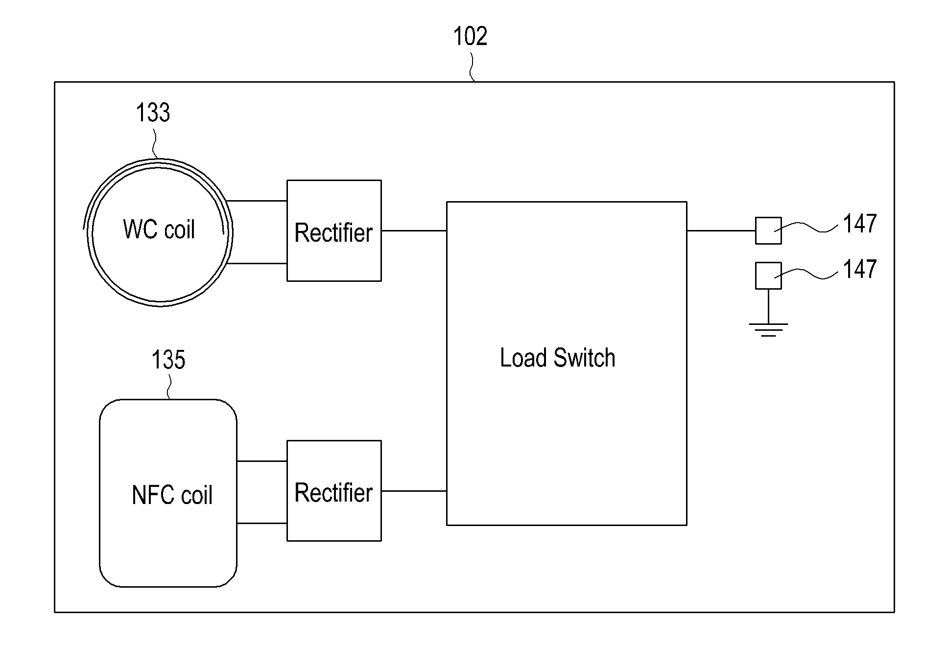
[0009]An aspect of embodiments of the present invention is to address at least the problems and / or disadvantages and to provide at least the advantages described below. Accordingly, an aspect of embodiments of the present invention is to provide a portable terminal having a structure that facilitates mounting of a secondary coil for wireless charging and a Near Field Communication (NFC) antenna element, without increasing the thickness of the portable terminal.
[0010]Another aspect of embodiments of the present invention is to provide a portable terminal having a structure that can achieve a sufficient wireless charging efficiency and a sufficient recognition distance for NFC.
[0011]A further aspect of embodiments of the present invention is to provide a portable terminal having a structure that facilitates fixing of a spirally wound coil or an antenna element having the same configuration as the coil.

Problems solved by technology

However, the use of a shielding body for each of the antenna element and the secondary coil increases the thickness of the portable terminal.
Although the secondary coil for wireless charging may be utilized as the NFC antenna element, it is difficult to achieve both wireless charging efficiency and a recognition distance for NFC.
Moreover, since the shielding body is usually formed by rolling to be in a planar form, it is difficult to fix a spirally wound coil or an antenna element having the same structure.

Method used


Image

  • Portable terminal having a wireless charger coil and an antenna element on the same plane
  • Portable terminal having a wireless charger coil and an antenna element on the same plane
  • Portable terminal having a wireless charger coil and an antenna element on the same plane

Examples


Embodiment Construction

[0023]Reference will now be made in detail to embodiments of the present invention with reference to the accompanying drawings. In the drawings, the same reference numerals will be understood to refer to the same elements, features and structures. In addition, a detailed description of a generally known function and structure of the present invention will be avoided lest it should obscure the subject matter of the present invention.

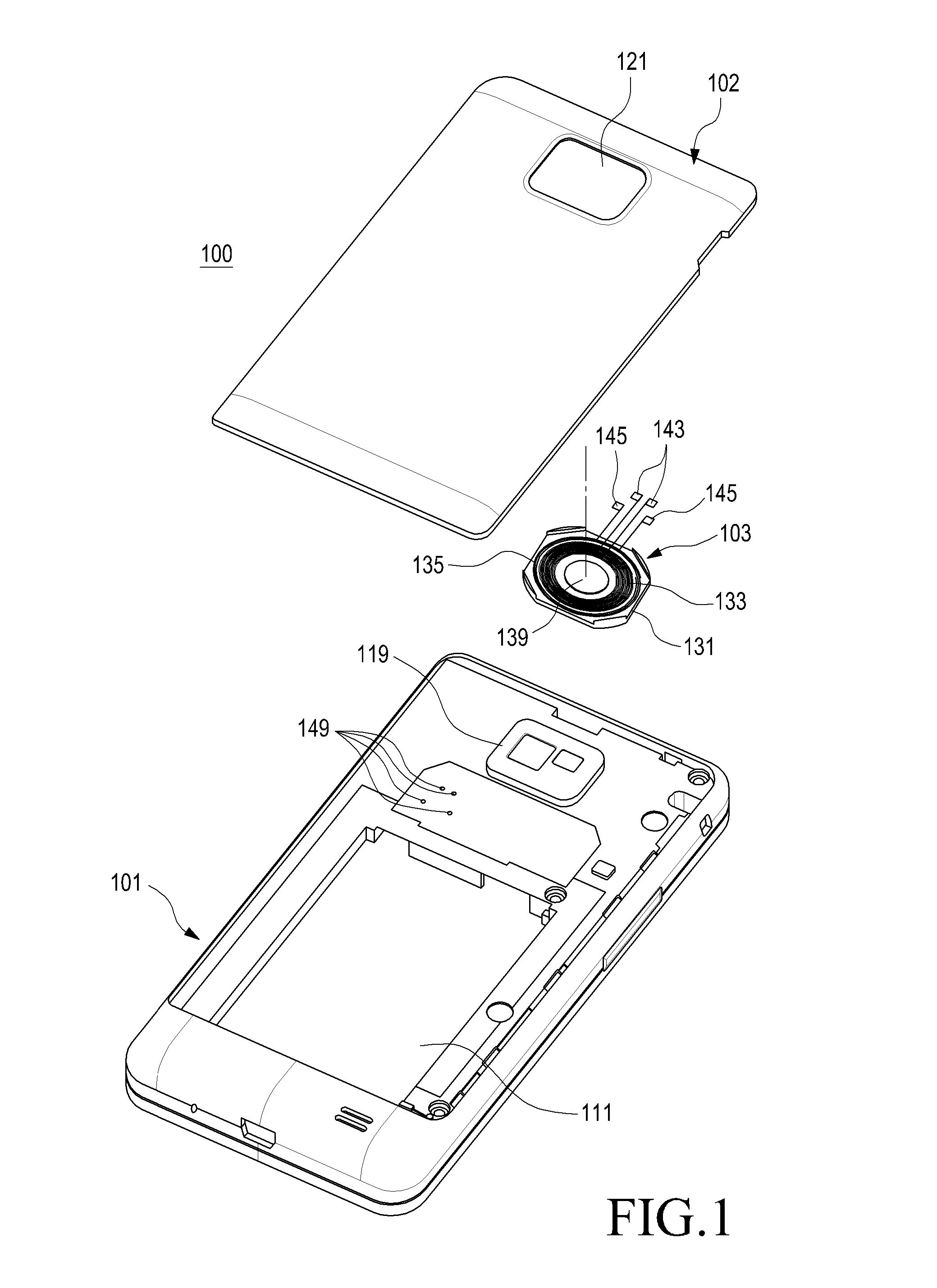
[0024]Referring to FIGS. 1-3, a portable terminal 100 according to an embodiment of the present invention includes a shielding member 131 attached to an inner surface of an external part such as a battery cover 102 or a housing 101, and a pair of coils 133 and 135 attached to the shielding member 131. The coils 133 and 135 are mounted on the same plane. The shielding member 131 and the coils 133 and 135 are collectively referred to herein as a coil module 103.

[0025]Referring to FIG. 1, the portable terminal 100 is a bar type terminal having a touch screen...


PUM

PropertyMeasurementUnit
frequencyaaaaaaaaaa
recognition distanceaaaaaaaaaa
areaaaaaaaaaaa

Abstract

A portable terminal having a wireless charger coil and an antenna element on the same plane is provided, in which a shielding member is attached to an inner surface of an external part, a first coil is attached to one surface of the shielding member, facing the inner surface of the external part, and a second coil is attached to the one surface of the shielding member, surrounding the first coil on the same plane.

Description

PRIORITY[0001]This application claims priority under 35 U.S.C. §119(a) to a Korean Patent Application filed in the Korean Intellectual Property Office on Aug. 8, 2011, and assigned Serial No. 10-2011-0078611, the contents of which are incorporated herein by reference.BACKGROUND OF THE INVENTION[0002]1. Field of the Invention[0003]The present invention relates to a portable terminal, and more particularly, to a portable terminal having a secondary coil for wireless charging, as well as a plurality of antenna elements.[0004]2. Description of the Related Art[0005]In general, a portable terminal is a device capable of performing a mobile communication function, an electronic note function, Internet access, and a multimedia function, among other functions, while being carried by a user. Recently, various functions have been integrated in a single mobile communication terminal called a smart phone.[0006]Meanwhile, a transport card, a security card, a credit card, and the like can be used ...

Claims


Application Information

Patent Timeline
Patent Type & Authority Patents(United States)
IPC IPC(8): H01M10/46H02J7/00
CPCH04M1/0262H02J7/0044H04M2250/04H01F38/14H02J7/00H02J7/025H04B5/00H04B5/0087H04B5/0075H04B5/0081H04B5/0037H02J50/10H02J50/90H02J50/70H01Q1/24H02J7/04H04W88/02
Inventor PARK, JIN-HYOUNGKIM, KI-HYUNKO, KIL-SOOPARK, SE-HOPARK, SUNG-KWEON
Owner SAMSUNG ELECTRONICS CO LTD
Learn More