
Zoom lens and imaging apparatus

a zoom lens and imaging apparatus technology, applied in the field of zoom lenses and imaging apparatuses, can solve the problems of difficult processing of lenses, small tolerances for production error and assembly error, and inability to realize cost reduction simply by reducing the number of lenses, so as to reduce the significance of zoom lenses, reduce the effect of brightness and difficulty in correction of spherical aberration

Inactive Publication Date: 2014-12-23
FUJIFILM CORP
View PDF30 Cites 0 Cited by
  • Summary
  • Abstract
  • Description
  • Claims
  • Application Information

AI Technical Summary

Benefits of technology

The proposed configuration achieves favorable optical performance and cost reduction by optimizing lens power distribution, ensuring effective aberration correction and maintaining a compact design, while securing a variable magnification ratio of 3× to 4×, thus addressing the limitations of existing zoom lenses.

Problems solved by technology

However, cost reduction cannot be realized simply by reducing the number of lenses.
For example, if a zoom lens is constituted by a small number of lenses, the power of each lens will become great, resulting in tolerances for production error and assembly error becoming small, processing of the lenses becoming difficult, etc.
As a result, there is a possibility that production costs will increase.
However, if a zoom lens is constituted by a small number of lenses, the power of each lens will become great.
Therefore, it will become difficult to employ less expensive plastic materials.
This is because variations in optical data and performance accompanying temperature changes will become great, and correction balance of aberrations will become difficult.

Method used


Image

  • Zoom lens and imaging apparatus
  • Zoom lens and imaging apparatus
  • Zoom lens and imaging apparatus

Examples


Embodiment Construction

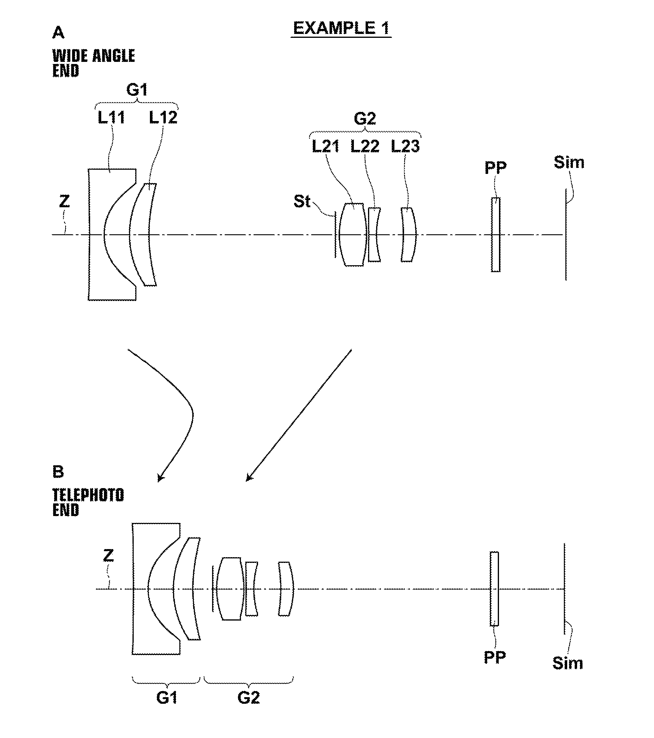
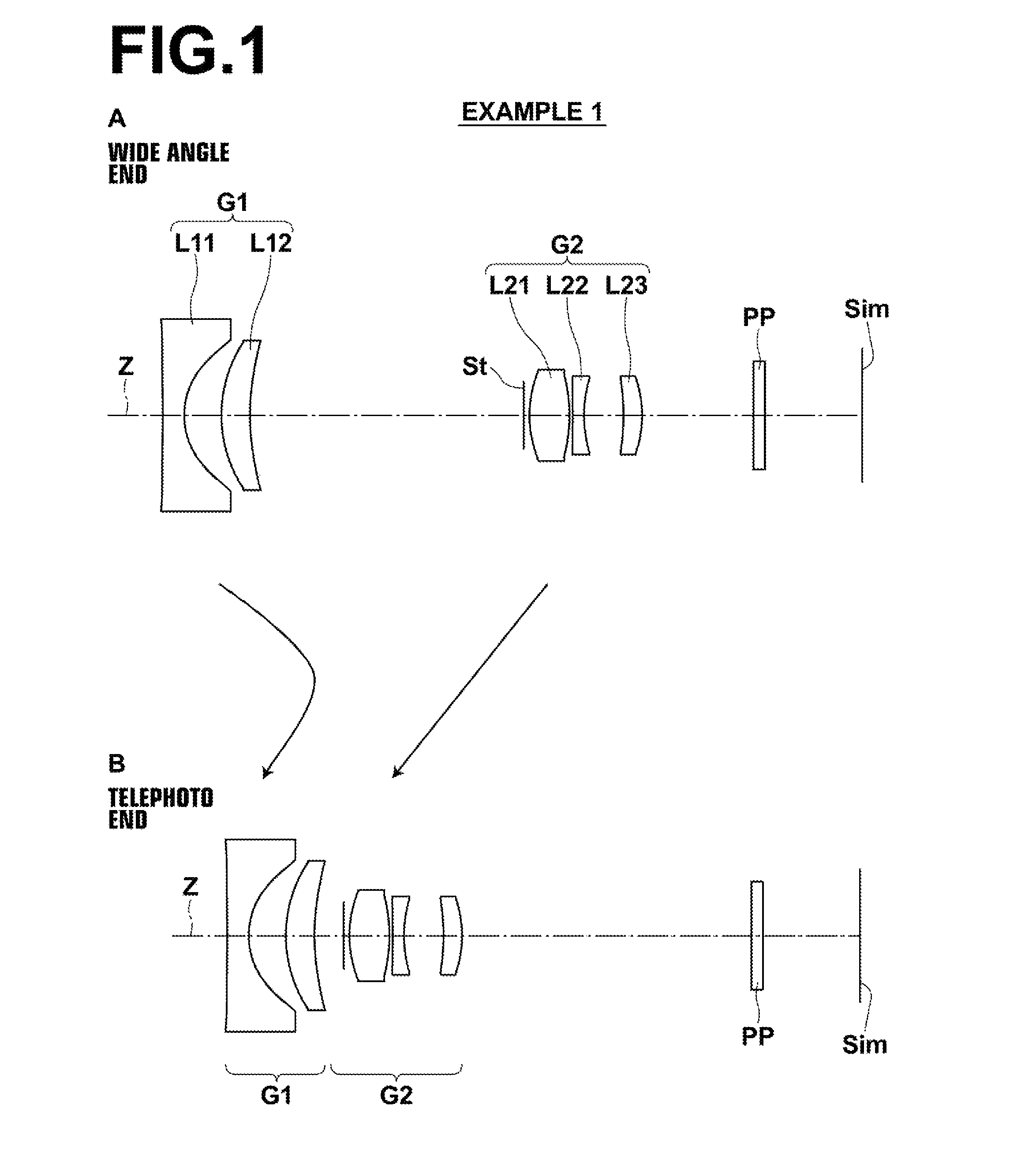
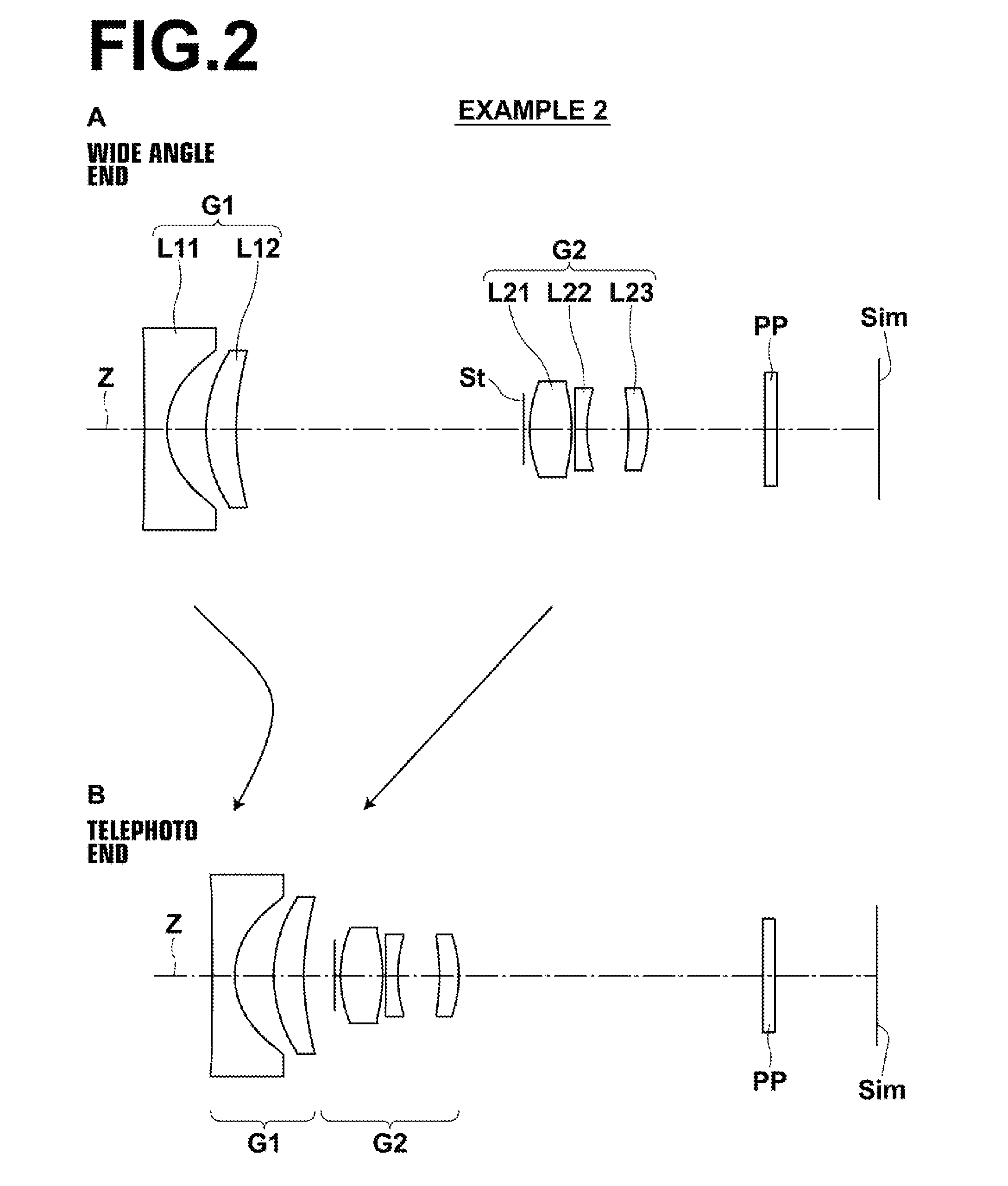
[0099]Hereinafter, embodiments of the present invention will be described in detail with reference to the attached drawings. FIG. 1 is a cross sectional diagram that illustrates the configuration of a zoom lens according to an embodiment of the present invention, and corresponds to a zoom lens of Example 1 to be described later. FIG. 2 through FIG. 11 are cross sectional diagrams that illustrate configurations of zoom lenses according to other embodiments of the present invention, and corresponds to zoom lenses of Examples 2 through 11 to be described later. The basic configurations of the embodiments illustrated in FIG. 1 through FIG. 11 are the same except that a second lens group G2 is constituted by two lenses in the embodiment of FIG. 10. The manners in which the configurations are illustrated are also the same. Therefore, the zoom lenses according to the embodiments of the present invention will be described mainly with reference to FIG. 1.

[0100]In FIG. 1, the left side is the...


PUM


Abstract

A zoom lens includes: a first lens group having a negative power; and a second lens group having a positive power, in this order from an object side. The first lens group includes a first lens having a negative power and a second lens having a positive power. The zoom lens satisfies conditional formulae 1.6<|f1| / fw<2.5 (1); 1.6<f2 / fw<2.4 (2); 0.32<d2 / fw<0.60 (3); 2.5<ft / fw<4.5 (4); 1.56<nd2<1.66 (5); and νd2<33 (6), when f1: the focal length of the first lens group, f2: the focal length of the second lens group, fw: the focal length of the entire system at the wide angle end, d2: the distance between the first and second lenses along an optical axis, ft: the focal length of the entire system at the telephoto end, nd2: the refractive index of the second lens at the d line, and νd2: the Abbe's number of the second lens at the d line.

Description

CROSS REFERENCE TO RELATED APPLICATIONS[0001]This application is a continuation of PCT / JP2012 / 004056 filed on Jun. 22, 2012, which claims foreign priority to Japanese Application No. 2011-140024 filed on Jun. 24, 2011. The entire contents of each of the above applications are hereby incorporated by reference.TECHNICAL FIELD[0002]The present invention is related to a zoom lens and an imaging apparatus. Particularly, the present invention is related to a zoom lens which can be favorably utilized in miniature cameras and portable terminal devices, and to an imaging apparatus equipped with such a zoom lens.BACKGROUND ART[0003]Conventionally, zoom lenses of the two group or the three group type having leading negative lens groups (a configuration in which negative lens groups are provided toward the object side) are well known as zoom lenses to be provided in compact digital cameras, compact video cameras, and portable terminal devices. For example, Japanese Unexamined Patent Publication...

Claims


Application Information

Patent Timeline
Patent Type & Authority Patents(United States)
IPC IPC(8): G02B3/02G02B9/08G02B15/14
CPCG02B15/177G02B27/646G02B13/04
Inventor KAWAMURA, DAIKI
Owner FUJIFILM CORP
Learn More