
Latency measurement

a technology of latency and measurement method, applied in the field of latency measurement, can solve the problems of inaccurate testing techniques of touchscreen displays and other touch-sensitive devices, and achieve the effect of measuring the latency of the devi

Active Publication Date: 2014-12-16
MICROSOFT TECH LICENSING LLC
View PDF176 Cites 11 Cited by
  • Summary
  • Abstract
  • Description
  • Claims
  • Application Information

AI Technical Summary

Benefits of technology

This patent describes techniques for measuring the delay of a device in detecting and responding to movement. This can be useful for testing the accuracy and responsiveness of touchscreen devices. The test apparatus uses a motor to move a contact near the sensors of the device, and modules to measure the time it takes for the device to recognize the movement. This can help in identifying any issues or bugs in the device's software, ensuring it works properly. The patent also describes different methods to measure this movement, such as using a laser and photo diode or a contact in a circular path. Overall, the patent aims to provide a reliable and efficient way to test the technical functionality of touchscreen devices.

Problems solved by technology

However, traditional techniques that were utilized to test touchscreen displays and other touch-sensitive devices were often inaccurate and therefore were typically inadequate to test the touchscreen displays as suitable for intended use of the device.

Method used


Image

  • Latency measurement
  • Latency measurement
  • Latency measurement

Examples


example environment

[0018

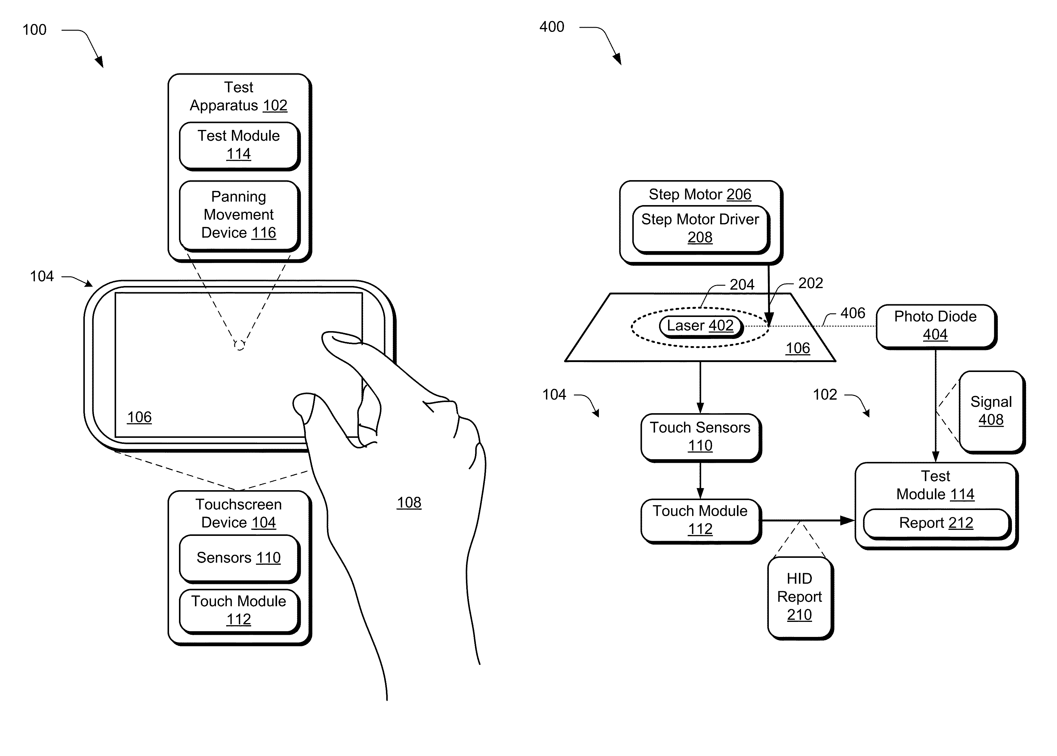
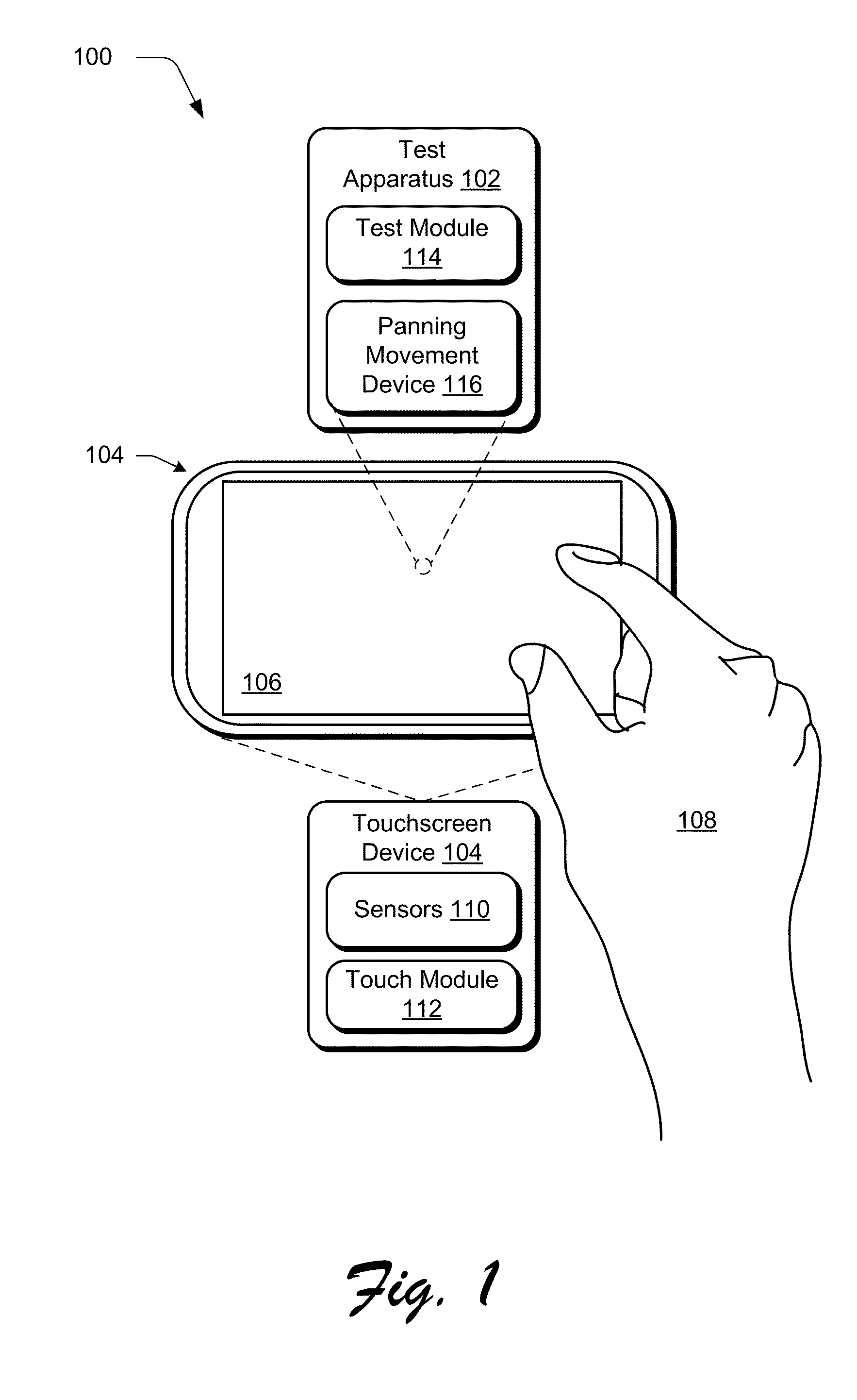
[0019]FIG. 1 depicts an environment 100 in an example implementation that includes a test apparatus 102 that is suitable to test a touchscreen device 104. The touchscreen device 104 may be configured in a variety of ways. For example, the touchscreen device 104 may be configured as part of a mobile communication device such as a mobile phone, a portable game-playing device, a tablet computer, as part of a traditional computing device (e.g., a display device that is part of a laptop or personal computer), and so on.

[0020]Additionally, the display device 106 of the touchscreen device 104 may be configured in a variety of ways. For example, the display device 106 of the touchscreen device 104 may include sensors that are configured to detect proximity (e.g., contact) with the display device 106. Sensors 110 are typically used to report actual contact with the display device 106, such as when being touched with a finger of a user's hand 108, although other sensors are also describe...

example procedures

[0193

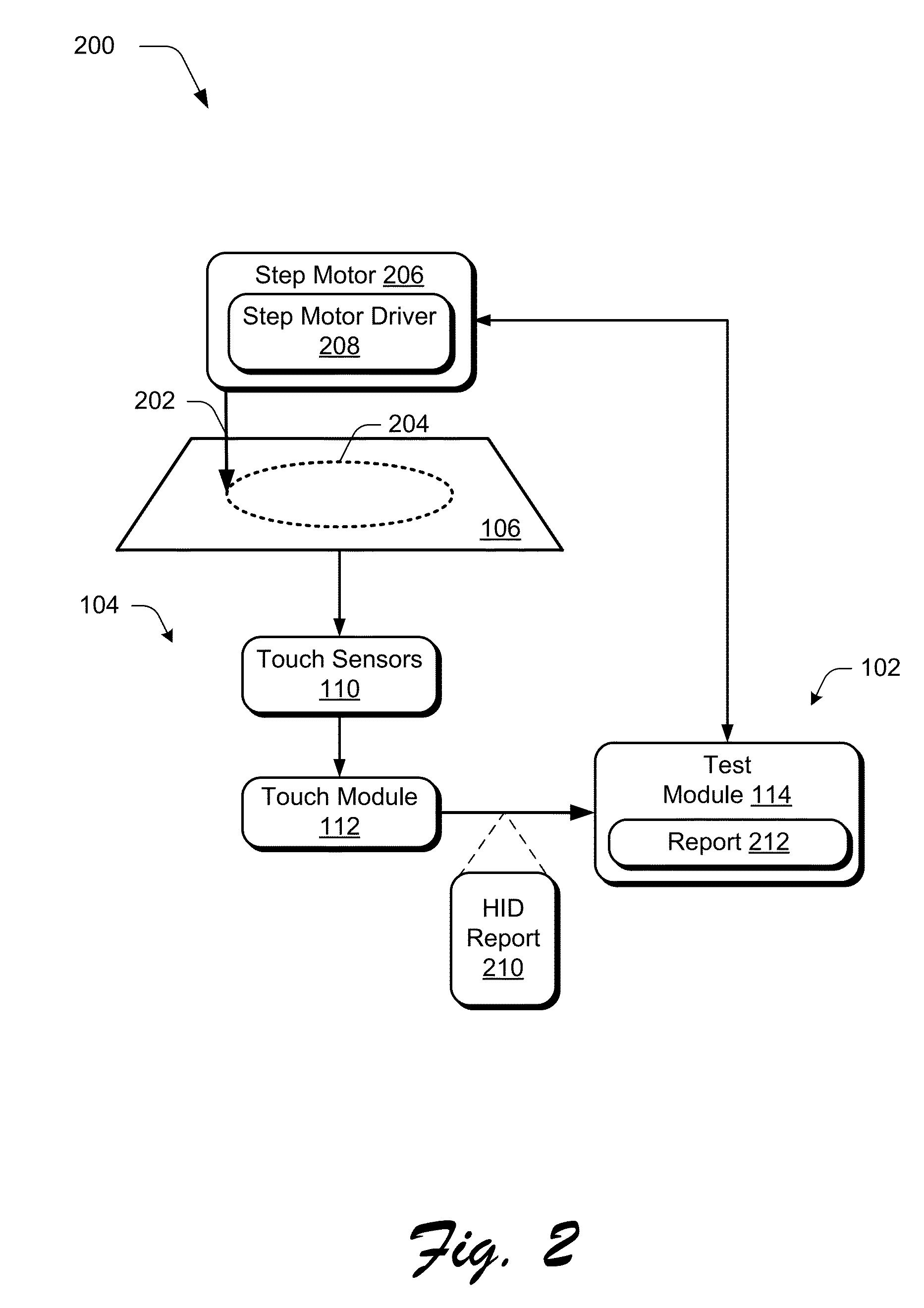
[0194]The following discussion describes panning latency measurement techniques that may be implemented utilizing the previously described systems and devices. Aspects of each of the procedures may be implemented in hardware, firmware, or software, or a combination thereof. The procedures are shown as a set of blocks that specify operations performed by one or more devices and are not necessarily limited to the orders shown for performing the operations by the respective blocks. In portions of the following discussion, reference will be made to the environment 100 of FIG. 1 and the systems 200-400 of FIGS. 2-4, respectively.

[0195]FIG. 5 depicts a procedure 500 in an example implementation in which latency is measured of a device in recognizing movement. Data is received by a test apparatus that describes panning movement detected using touch functionality of a device (block 502). A device under test, for instance, may provide an output to the test module 114, such as an HID rep...


PUM


Abstract

Panning latency measurement techniques are described. In one or more implementations, a test apparatus includes one or more motors configured to move one or more contacts at least proximal to one or more sensors of a device to be detectable as a movement. The test apparatus also includes one or more modules implemented at least partially in hardware to measure latency of the device to recognize the movement of the one or more contacts.

Description

BACKGROUND[0001]Display and input techniques utilized by computing devices are ever evolving. For example, initial computing devices were provided with monitors. A user interacted with the computing device by viewing simple text on the monochrome monitor and entering text via a keyboard that could then be viewed on the monitor. Other techniques were then subsequently developed, such as graphical user interfaces and cursor control devices.[0002]Display and input techniques have continued to evolve, such as to sense touch using a touchscreen display of a computing device to recognize gestures. A user, for instance, may interact with a graphical user interface by inputting a gesture using the user's hand that is detected by the touchscreen display or other touch-sensitive device. However, traditional techniques that were utilized to test touchscreen displays and other touch-sensitive devices were often inaccurate and therefore were typically inadequate to test the touchscreen displays ...

Claims


Application Information

Patent Timeline
Patent Type & Authority Patents(United States)
IPC IPC(8): G06F3/043G06F3/041G06F11/30G21C17/00
CPCG06F3/041G06F3/0418
Inventor UZELAC, ALEKSANDARSTEVENS, DAVID A.BATCHVAROV, ANDREY B.LEE, CHANGSINSHIGEMITSU, TAKAHIRO
Owner MICROSOFT TECH LICENSING LLC
Learn More