
Method and system for controlling an uplink transmitting power, and a base station

a transmission power and transmission system technology, applied in the field of communication, can solve the problems of affecting the uplink performance of the wireless communication system, restricting the flexibility of controlling the uplink interference between, etc., and achieve the effect of improving the uplink performance of the system

Active Publication Date: 2014-12-09
ZTE CORP
View PDF11 Cites 0 Cited by
  • Summary
  • Abstract
  • Description
  • Claims
  • Application Information

AI Technical Summary

Benefits of technology

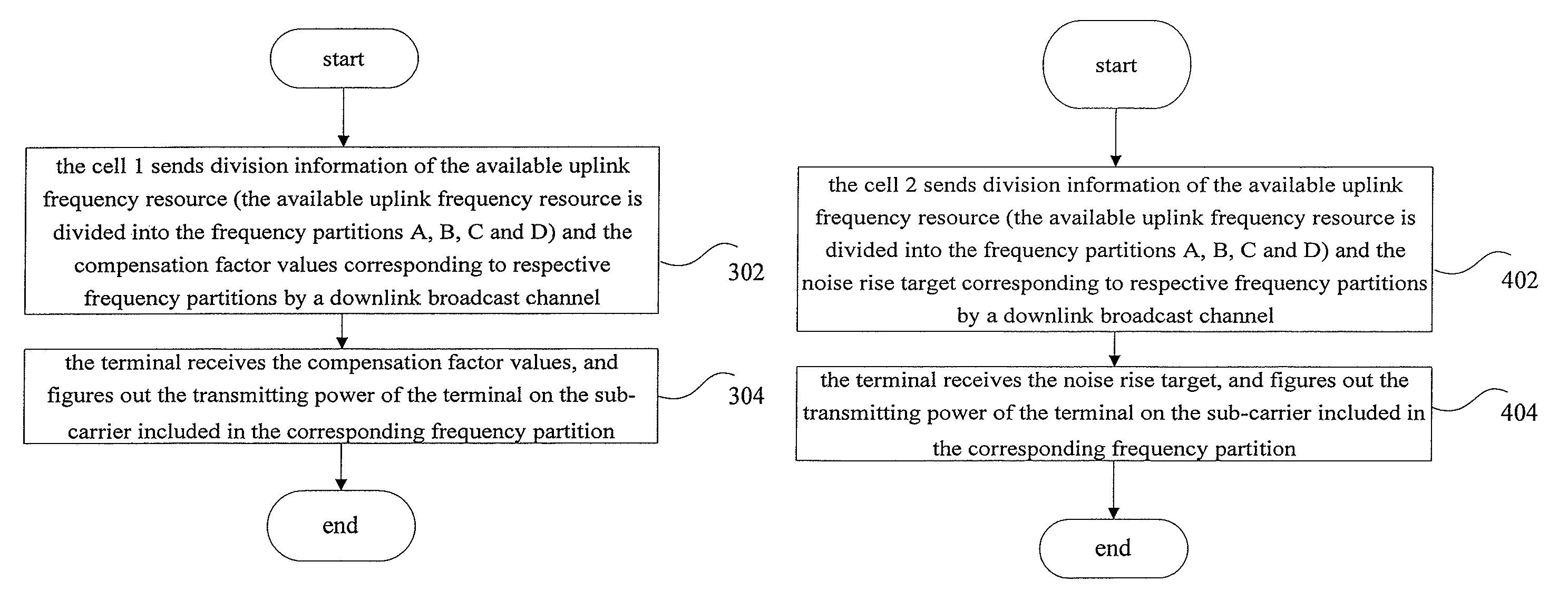
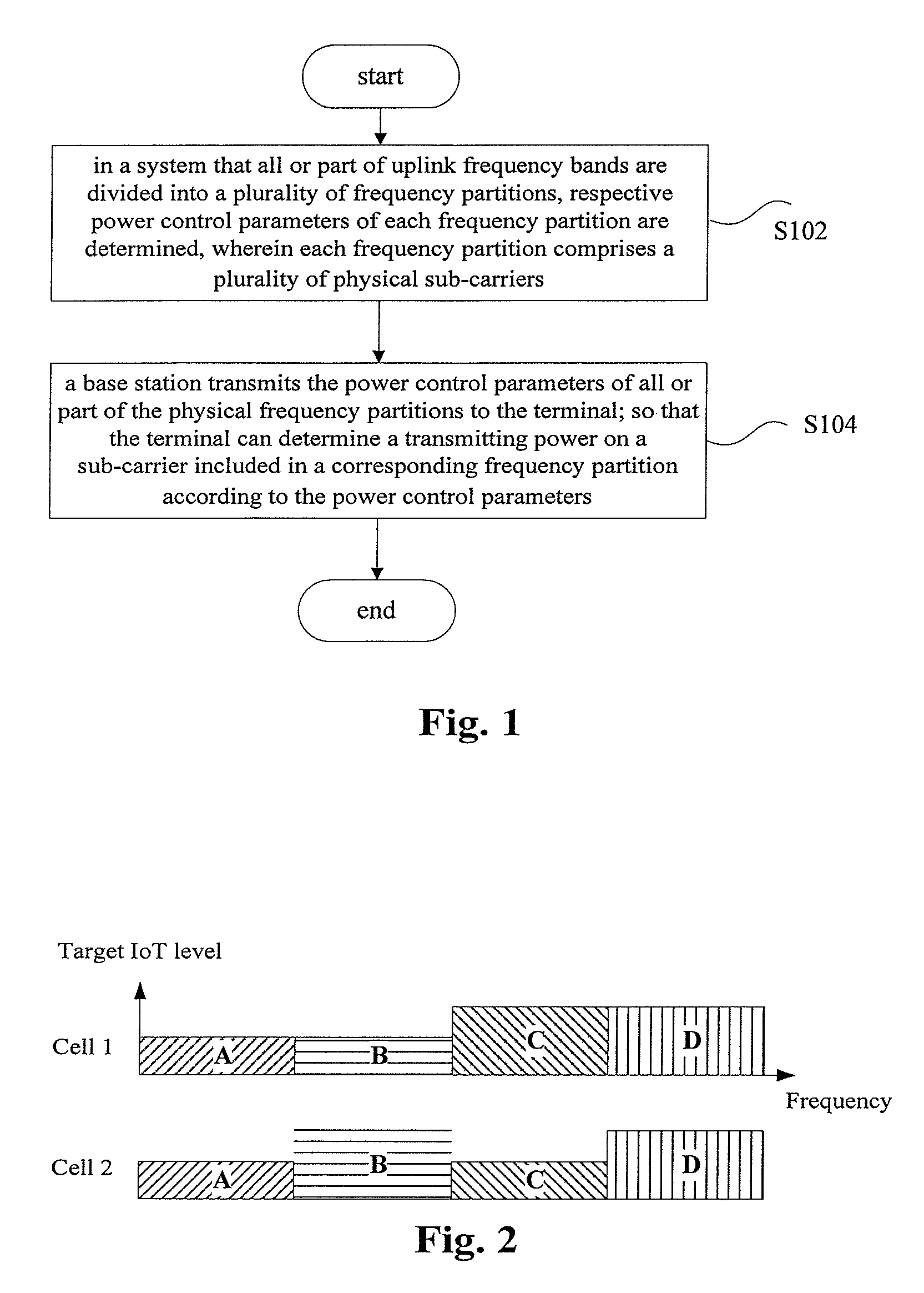
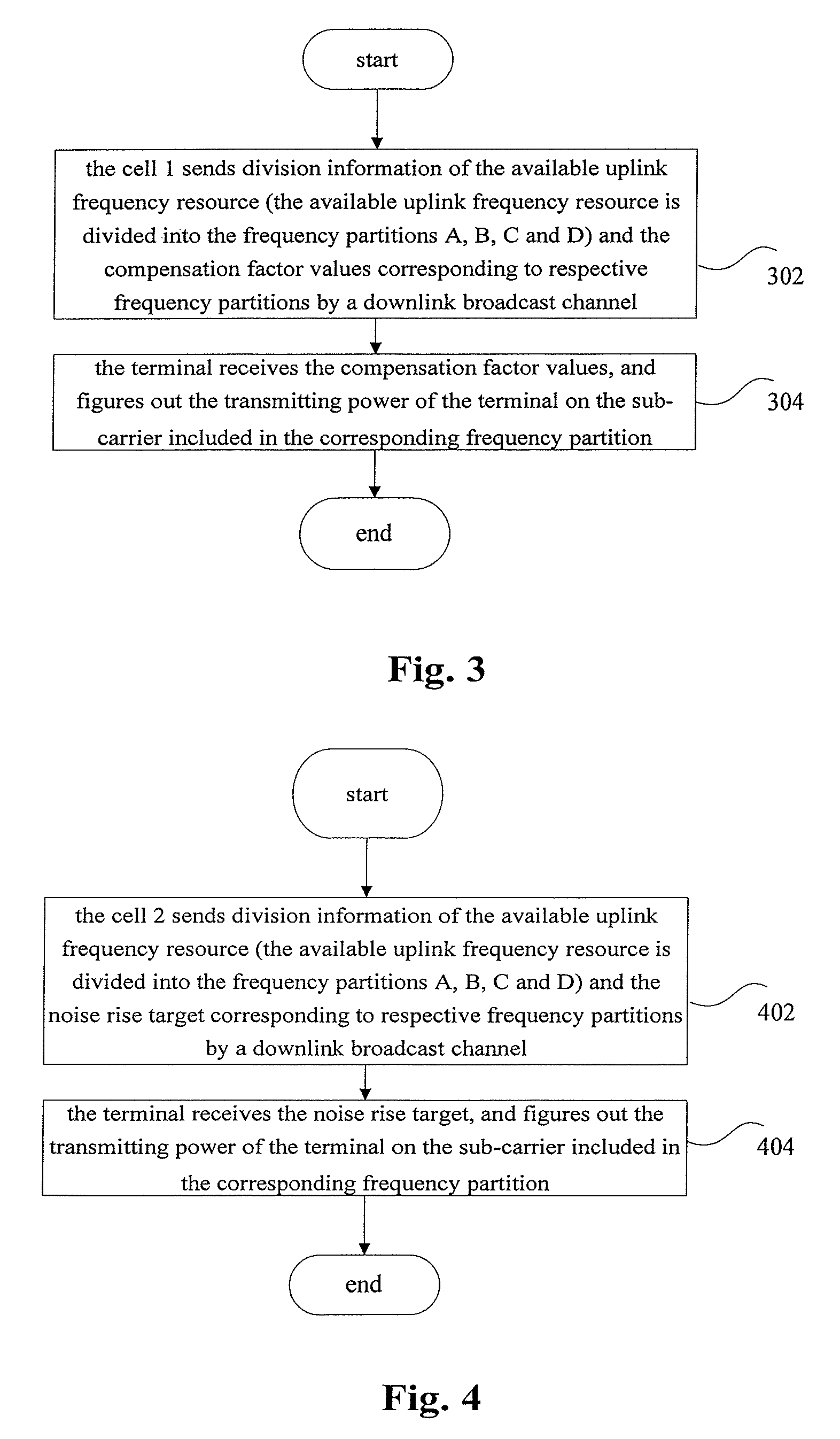
The present invention solves the problem of inflexible and ineffective uplink power control methods in related technology. It allows the terminal to determine the optimal transmitting power for each sub-carrier in the uplink frequency band based on power control parameters. This ensures efficient and effective control of uplink interference between cells and improves overall uplink performance.

Problems solved by technology

However, due to the mutual interference between the users using the same frequency resources in each cell, the uplink interference between the cells has a strong impact on the uplink performance of the wireless communication system.
In this way, the uplink transmitting power is determined by one resource description variable of the uplink frequency, which will restrict the flexibility of controlling the uplink interference between the cells, and impact the uplink performance of the wireless communication system.

Method used


Image

  • Method and system for controlling an uplink transmitting power, and a base station
  • Method and system for controlling an uplink transmitting power, and a base station
  • Method and system for controlling an uplink transmitting power, and a base station

Examples


embodiment

Apparatus Embodiment

[0086]A base station is provided according to an embodiment of the present invention. Preferably, the base station can be used for realizing the method for controlling the uplink transmitting power provided in the above method embodiments.

[0087]FIG. 5 shows a structure of the base station according to a device embodiment of the present invention. As shown in FIG. 5, the base station comprises a first determining module 2 and a transmitting module 4. The functions of the above modules will be described in detail hereinafter.

[0088]The first determining module 2 is adapted to determine the power control parameters of each frequency partition. Preferably, the power control parameters can be the compensation factor or the noise rise target. Preferably, the first determining module 2 is further adapted to determine the power control parameters of each corresponding frequency partition according to an excepted IoT of the adjacent cells in each frequency partition.

[0089]...

system embodiment

[0092]A system for controlling an uplink transmitting power is provided according to an embodiment of the present invention. The system for controlling the uplink transmitting power comprises a base station and a terminal. Preferably, the base station can be used for realizing the method for controlling the uplink transmitting power provided in the above method embodiments.

[0093]FIG. 6 shows the structure of the system for controlling the uplink transmitting power according to the system embodiment of the present invention. As shown in FIG. 6, the system for controlling the uplink transmitting power according to the system embodiment of the present invention comprises the base station 3 and the terminal 5. The functions of the above modules will be described in detail hereinafter.

[0094]The base station 3 comprises: a first determining module which is adapted to determine power control parameters of each frequency partition; and a transmitting module which is connected with the first...


PUM


Abstract

The present invention discloses a method and a system for controlling an uplink transmitting power, and a base station, wherein the method comprises: determining respective power control parameters of each frequency partition in a system whose uplink frequency band is divided into a plurality of frequency partitions, wherein each frequency partition comprises a plurality of physical sub-carriers; and a base station transmitting the power control parameters of all or part of the frequency partitions to a terminal, so that the terminal determines a transmitting power on a sub-carrier included in a corresponding frequency partition according to the power control parameters. By using the present invention, the power control parameters of a plurality of frequency partitions of an uplink frequency band are transmitted to the terminal, so that the terminal determines the transmitting power on the sub-carrier included in the corresponding frequency partition according to the power control parameters, which can solve the problems that the methods for controlling the uplink transmitting power in related technology is not flexible and can not effectively improve the uplink performance of the system, and can achieve the aims of controlling the uplink interference between the cells effectively and improving the uplink performance of the system.

Description

CROSS-REFERENCE TO THE RELATED APPLICATION[0001]This application is a National Stage Application of International Application No. PCT / CN2009 / 070777, filed Mar. 13, 2009, which designates the United States and claims priority to Chinese Application No. 200810172306.8, filed Mar. 31, 2008, the contents of each of which are incorporated by reference in their entirety.FIELD OF THE INVENTION[0002]The present invention relates to the communication field, in particular to a method and a system for controlling an uplink transmitting power, and a base station.BACKGROUND OF THE INVENTION[0003]In a wireless communication system, a base station refers to a device which provides services for a terminal. The base station communicates with the terminal through an uplink / a downlink, wherein the downlink (forward direction) refers to the direction from the base station to the terminal, and the uplink (backward direction) refers to the direction from the terminal to the base station. A plurality of t...

Claims


Application Information

Patent Timeline
Patent Type & Authority Patents(United States)
IPC IPC(8): H04W72/08H04L5/00H04W52/42H04W52/54H04B7/00H04W52/24H04W52/14H04W72/04H04W72/54
CPCH04W52/243H04W52/146H04L5/0007H04L5/0053H04W72/082H04W72/085H04W52/42H04W52/54H04W72/0473H04W72/541H04W72/542H04W88/08
Inventor LU, ZHAOHUAHAO, PENGXUE, YANLIU, YINGLIU, KUN
Owner ZTE CORP
Learn More