
Control apparatus and control method for internal combustion engine

a control apparatus and internal combustion engine technology, applied in mechanical devices, electric control, machines/engines, etc., can solve the problems of unnecessary fuel consumption, unfavorable combustion of fuel, and inevitably lean air/fuel ratio, so as to reduce the sense of strangeness caused

Active Publication Date: 2014-12-09
TOYOTA JIDOSHA KK
View PDF13 Cites 2 Cited by
  • Summary
  • Abstract
  • Description
  • Claims
  • Application Information

AI Technical Summary

Benefits of technology

The invention provides a control system for an internal combustion engine that reduces the feeling of strangeness for vehicle occupants. This is achieved by allowing the fuel cut to continue even when it would normally be restricted, which avoids the alternations between restrictions and execution of the fuel cut. This reduces the impact on the catalyst and other components in the engine. Additionally, the system also monitors the temperature of the catalyst and will continue the fuel cut if the temperature reaches a certain threshold. This ensures that the fuel cut is executed without causing any issues to the engine or its occupants.

Problems solved by technology

In some cases, the fuel cut may restrain unnecessary consumption of fuel.
During execution of the fuel cut, the air / fuel ratio inevitably becomes lean.
Consequently, the emissions purifying performance of the catalyst may decline.
Intermittent repetitions of execution of the fuel cut in the foregoing manner may intermittently cause vibration and noise of the internal combustion engine.
As a result, discomfort or sense of strangeness may be caused to an occupant of the vehicle.

Method used


Image

  • Control apparatus and control method for internal combustion engine
  • Control apparatus and control method for internal combustion engine
  • Control apparatus and control method for internal combustion engine

Examples


Embodiment Construction

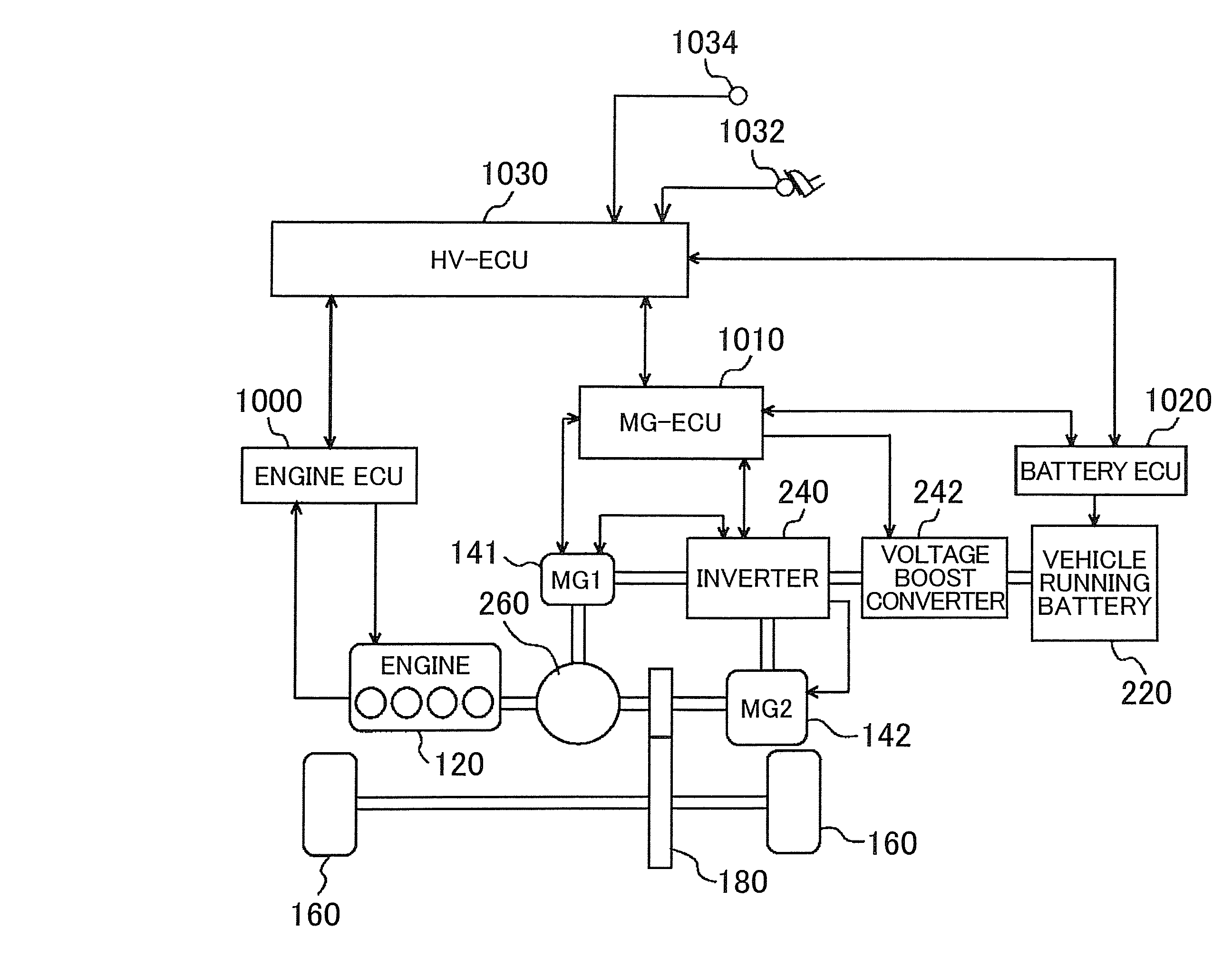
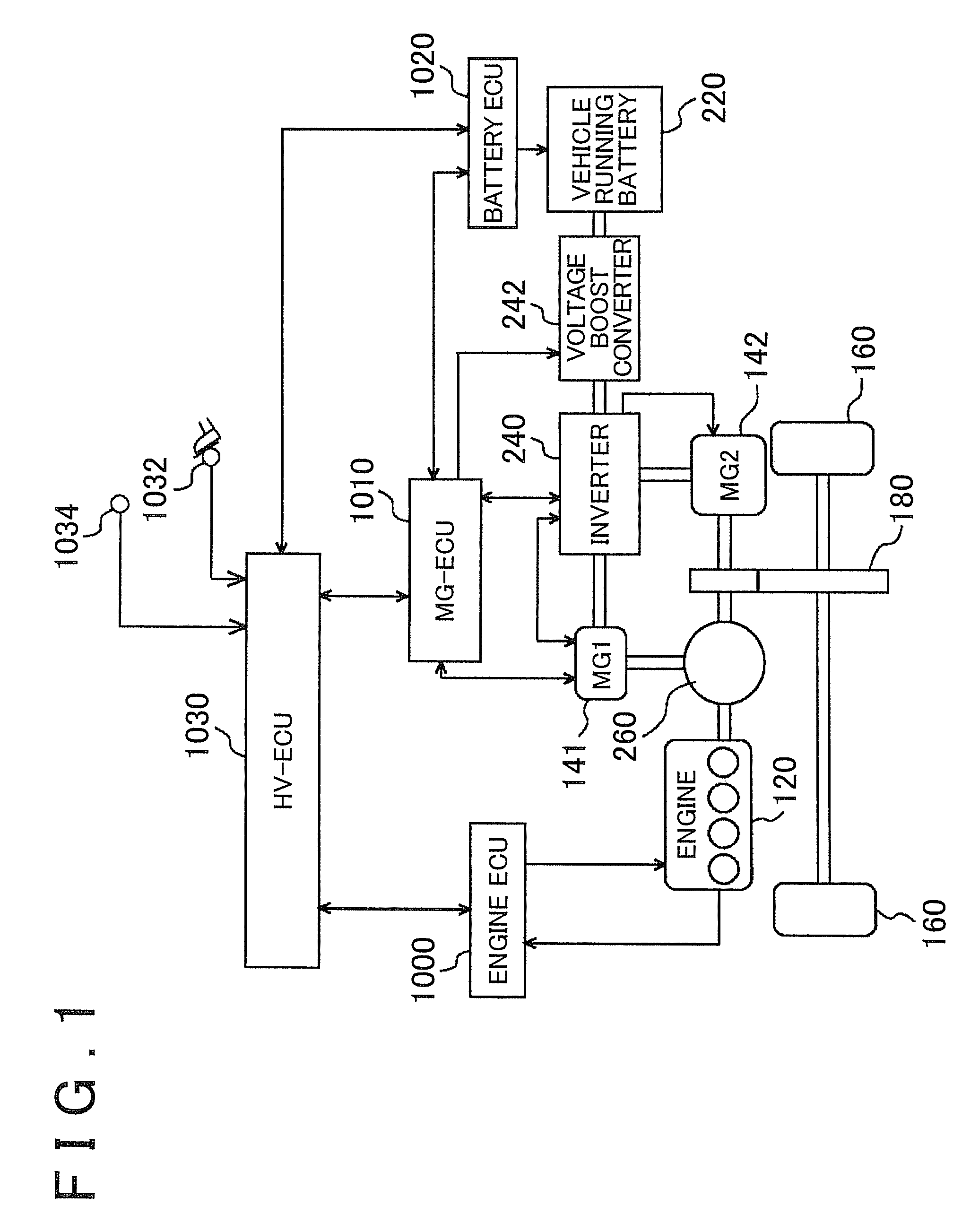
[0030]Embodiments of the invention will be described hereinafter with reference to the drawings. In the following description, the same component parts are denoted by the same reference characters. The names and functions thereof are also the same. Therefore, detailed descriptions of the same component parts will not be repeated.

[0031]With reference to FIG. 1, a hybrid vehicle shown as an example of a vehicle will be described. The invention may also be applied to a vehicle other than the hybrid vehicle.

[0032]A hybrid vehicle of this embodiment includes an internal combustion engine (hereinafter, simply referred to as engine) 120 provided with a plurality of cylinders, a first motor-generator 141 and a second motor-generator 142. The internal combustion engine is, for example, a gasoline engine, a diesel engine, etc. As a drive source of the hybrid vehicle of the embodiment, the engine 120 and the second motor-generator 142, as for examples, are used. That is, the hybrid vehicle run...


PUM


Abstract

An engine ECU diagnoses the presence or absence of abnormality during execution of the fuel cut. The engine ECU is configured to restrict the fuel cut according to the temperature of a catalyst when the temperature is higher than a fuel-cut-restriction temperature of the catalyst. The engine ECU is configured to set the fuel-cut-restriction temperature is lower when the diagnosis has been completed than when the diagnosis has not been completed. Furthermore, the engine ECU continues the fuel cut if the diagnosis is completed during execution of the fuel cut while the temperature of the catalyst is between the fuel-cut-restriction temperature set prior to the completion of the diagnosis and the fuel-cut-restriction temperature set after the completion of the diagnosis.

Description

INCORPORATION BY REFERENCE[0001]The disclosure of Japanese Patent Application No. 2012-158569 filed on Jul. 17, 2012 including the specification, drawings and abstract is incorporated herein by reference in its entirety.BACKGROUND OF THE INVENTION[0002]1. Field of the Invention[0003]The invention relates to a control apparatus and a control method for an internal combustion engine.[0004]2. Description of Related Art[0005]A fuel cut control in which fuel injection and ignition are temporarily stopped at the time of deceleration or the like is known. In some cases, the fuel cut may restrain unnecessary consumption of fuel. During execution of the fuel cut, the air / fuel ratio inevitably becomes lean. This makes it possible to diagnose the presence or absence of abnormality of an air / fuel ratio sensor, or the like, on the basis of whether during execution of the fuel cut, the output of the air / fuel ratio sensor shows that the air / fuel ratio is lean.[0006]If the fuel cut is executed, for...

Claims


Application Information

Patent Timeline
Patent Type & Authority Patents(United States)
IPC IPC(8): F02D41/12F01N11/00F01N3/00F02D41/14F02D41/22F02D29/02F01N3/10
CPCF01N11/002F02D29/02F01N3/10F02D41/1495Y02T10/40F01N2900/1602F02D41/123F02D41/222F02D2200/0802Y02T10/47
Inventor SASAKI, TOSHITAKE
Owner TOYOTA JIDOSHA KK
Learn More