Automated tightening shoe

Active Publication Date: 2014-12-09
HANDS FREE ENTERPRISES LLC
View PDF81 Cites 52 Cited by
  • Summary
  • Abstract
  • Description
  • Claims
  • Application Information

AI Technical Summary

Benefits of technology

The invention is an automated tightening shoe that can be snugly tightened and loosened easily without use of the wearer's hands. It contains a sole and a shoe upper with a lace that is pulled by a tightening mechanism in a crisscrossed fashion across the tongue to secure the shoe around the foot. The mechanism is located inside the shoe sole and includes a rotatable axle, a roller wheel, and a ratchet wheel with teeth. A pawl engages the ratchet teeth to prevent the axle from counter-rotating. However, when the wearer engages a release lever, the pawl is pivoted out of engagement with the teeth, allowing the shoe lace to be easily tightened or loosened. The shoe lace can be easily replaced without access to the tightening mechanism.

Problems solved by technology

This can be a hassle for the ordinary wearer.
Moreover, young children may not know how to tie a knot in the shoe lace, thereby requiring assistance from an attentive parent or caregiver.
Furthermore, elderly people suffering from arthritis may find it painful or unduly challenging to pull shoe laces tight and tie knots in order to secure shoes to their feet.
These mechanisms are complicated in their number of parts needed to operate in unison.
However, such tension lever or push plate may not have constant pressure applied to it by the foot, which will result in loosening of the tightening cable or strap.
Moreover, the wearer may find it uncomfortable to step on the tension lever or push plate throughout the day.
But, such a battery-operated device can suffer from short circuits, or subject the wearer to a shock in a wet environment.
But, such Velcro closures can frequently become disconnected when too much stress is applied by the foot.
Moreover, Velcro closures can become worn relatively quickly, losing their capacity to close securely.
Furthermore, many wearers find Velcro straps to be aesthetically ugly on footwear.
However, none of the automated tightening systems heretofore devised has been entirely successful or satisfactory.
Major shortcomings of the automated tightening systems of the prior art are that they fail to tighten the shoe from both sides so that it conforms snugly to the wearer's foot, and that they lack any provision for quickly loosening the shoe when it is desired to remove the shoe from the wearer's foot.
Moreover, they frequently suffer from: (1) complexity, in that they involve numerous parts; (2) the inclusion of expensive parts, such as small electric motors; (3) the use of parts needing periodic replacement, e.g. a battery; or (4) the presence of parts requiring frequent maintenance.
However, because the laces are physically secured to the tightening mechanism contained within a chamber of the shoe sole, they cannot be replaced should they fray or break.
This shortens the useful life of the shoe product.
However, this type of convertible roller skating shoe does not contain an automated tightening mechanism, let alone use the roller wheel to actuate such a mechanism.

Method used


Image

  • Automated tightening shoe
  • Automated tightening shoe
  • Automated tightening shoe

Examples


embodiment 233

[0054]FIGS. 13-15 show an alternative embodiment 233 of first end shaft 232 or second end shaft 234. it is similar in design and construction to the end shaft depicted in FIGS. 7, 8, and 11 with the exception of an additional containment disk wall 288 molded between inner cylindrical shoulder 264 and outer cylindrical boss 266. This containment disk wall has a diameter that is larger than the diameter of the inner cylindrical shoulder. In this manner, containment disk wall 288 and disk portion 260 of end shaft 233 cooperate to define a region 289 for winding and unwinding lace 136 or engagement cable 196, while the containment disk wall 288 prevents undue lateral migration of the lace 136 or engagement cable 196. This helps to prevent the lace or engagement cable from getting tangled in the axle assembly 224, and impeding its rotational movement.

[0055]FIG. 9 shows actuator wheel 212 secured to wheel shaft 230. Actuator wheel 212, as shown more clearly in FIG. 8, contains a channel 2...

embodiment 210

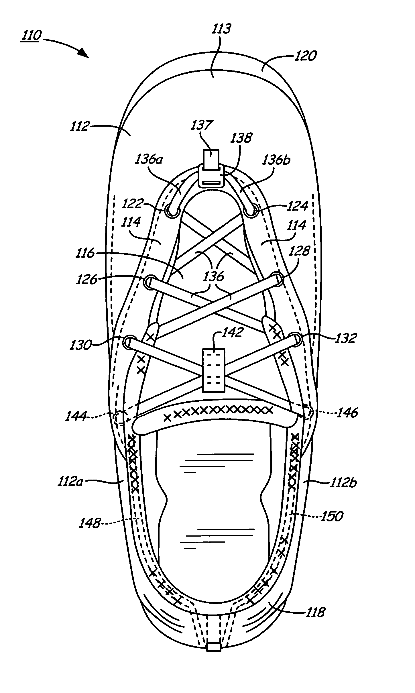
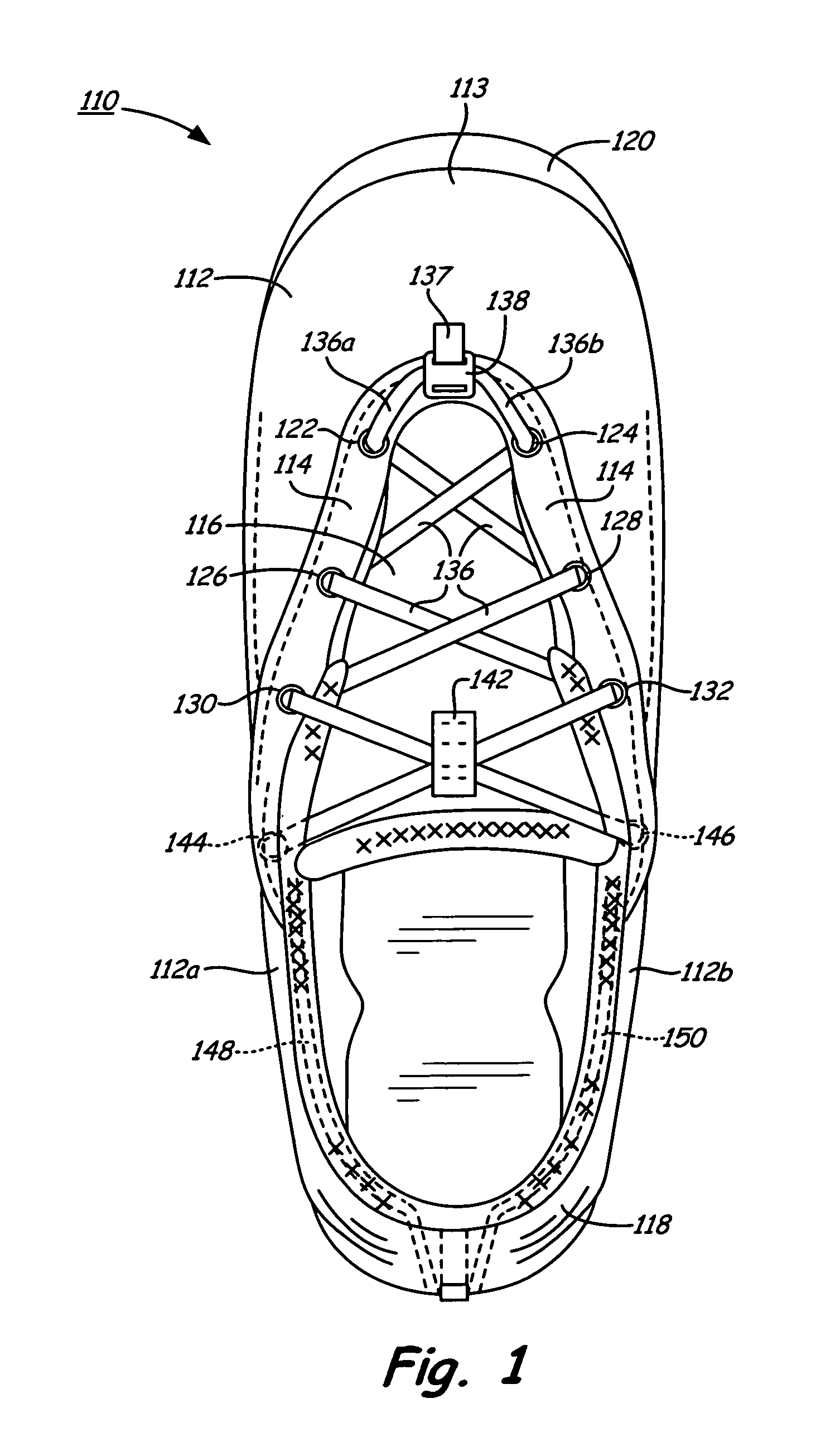
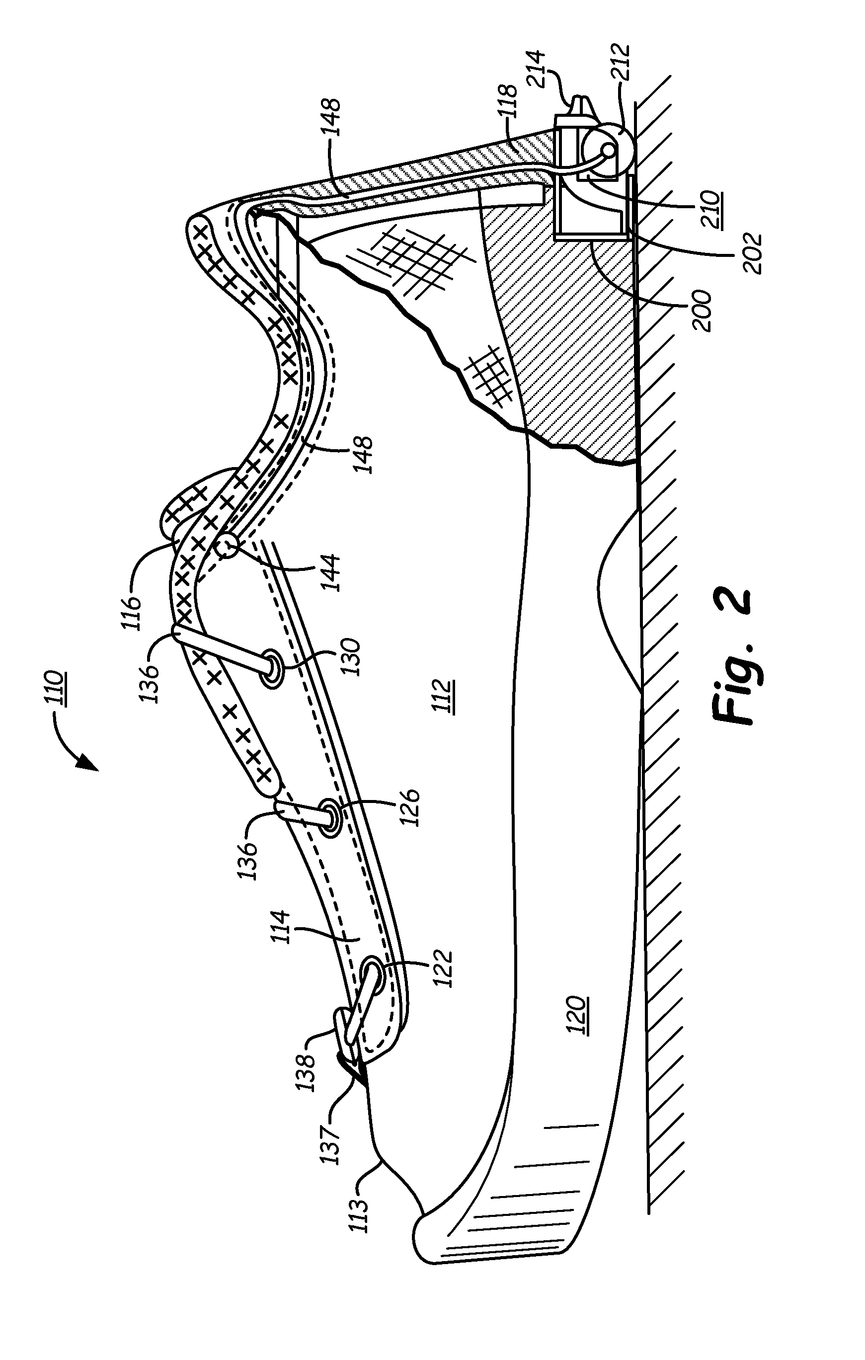
[0074]The automated tightening mechanism 210 of the present invention is simpler in design than other devices known within the industry. Thus, there are fewer parts to assemble during shoe manufacture and to break down during usage of the shoe. Another substantial advantage of the automated tightening mechanism embodiment 210 of the present invention is that shoe lace 136 and their associated guide tubes may be threaded down the heel portion of the shoe upper, instead of diagonally through the medial and lateral uppers. This feature greatly simplifies manufacture of shoe 110. Moreover, by locating automated tightening mechanism 210 closer to the heel within shoe sole 120, a smaller housing chamber 200 may be used, and the unit may more easily be inserted and glued into a smaller recess within the shoe sole during manufacture.

[0075]Another significant advantage of the automated tightening mechanism 210 of the present invention is the fact that a single shoe lace 136 is used to tighte...


PUM


Abstract

An automated tightening shoe with a single crisscrossed laces or closure panel and a tightening mechanism which operates in one direction to cause automatic tightening of the crisscrossed laces or closure panel to tighten the shoe about a wearer's foot, and which can be released easily so that the shoe can be removed from the wearer's foot. An actuating wheel partially projecting from the rear sole of the shoe provides a convenient and reliable actuating means for movement of the automated tightening mechanism in the tightening direction.

Description

FIELD OF THE INVENTION[0001]The present invention pertains to a shoe and, more particularly, to an automated tightening shoe. The shoe is provided with an automated tightening system, including a tightening mechanism which operates in one direction to cause automatic tightening of the shoe about a wearer's foot, and which can be released easily so that the shoe can be readily removed from the wearer's foot. The invention is chiefly concerned with an automated tightening shoe of the sport or athletic shoe variety, but the principles of the invention are applicable to shoes of many other types and styles.BACKGROUND OF THE INVENTION[0002]Footwear, including shoes and boots, are an important article of apparel. They protect the foot and provide necessary support, while the wearer stands, walks, or runs. They also can provide an aesthetic component to the wearer's personality.[0003]A shoe comprises a sole constituting an outsole and heel, which contact the ground. Attached to a shoe that...

Claims


Application Information

Patent Timeline
IPC IPC(8): A43C11/00A43B11/00A43B23/28A43B5/04
CPCA43B5/04A43B11/00A43B23/28A43C11/00A43C11/165
Inventor JOHNSON, GREGORY, G
Owner HANDS FREE ENTERPRISES LLC
Why Eureka
Try Eureka