Method and apparatus for detecting coding artifacts in an image

a technology of coding artifacts and images, applied in the field of methods and apparatus for detecting coding artifacts in images, can solve the problems of content quality loss, very limited data rate and storage capacity, and low resolution and frame rate of distributed video content, and achieve the effect of reducing coding artifacts, simple and reliable, and fas

Inactive Publication Date: 2014-11-11
SONY CORP
View PDF16 Cites 2 Cited by
  • Summary
  • Abstract
  • Description
  • Claims
  • Application Information

AI Technical Summary

Benefits of technology

[0008]It is an object of the present invention to provide a fast, simple and reliable method and an apparatus for detecting coding artifacts in an image. It is a further object of the present invention to provide a corresponding method and apparatus for reducing coding artifacts in an image and a corresponding device for processing and / or displaying an image. Still further, it is an object of the present invention to provide a corresponding computer program for implementing said methods and a computer readable non-transitory medium.
[0013]The present invention is based on the idea to determine the area(s) with in the image, i.e. the so-called artifact area(s), where the occurrence probability of coding artifacts, in particular of ringing artifacts and / or mosquito noise, is high. For this purpose edges, in particular prominent edges, are determined, since it has been recognized that in the vicinity of prominent edges those artifacts occur. Further, according to the present invention borders between texture areas and flat areas are determined, those texture areas including potential artifacts. The areas between those determined edge positions and said border positions are then defined as artifact areas, which potentially comprises coding artifacts. In this way, those artifact areas can be quickly and reliably determined with only a low amount of processing capacity.
[0017]reducing coding artifacts in said block noise filtered image by applying a step of mosquito noise reduction and / or deringing to only the detected artifact areas of the image.

Problems solved by technology

In both distribution systems the content may suffer a loss of quality due to limited bandwidth and / or storage capacity.
Especially in some internet based video services as video portals (e.g. YouTube™) the allowed data rate and storage capacity is very limited.
Thus, the resolution and frame rate of the distributed video content may be quite low.
Furthermore, lossy source coding schemes may be applied to the video content (e.g. MPEG2, H.263, MPEG4 Video, etc.), which also negatively affect the video quality and lead to losses of some essential information (e.g. textures or details).
Coding artifacts are not comparable to conventional errors such as additive Gaussian noise.
Therefore, conventional techniques for error reduction and image enhancement may not be directly transferred to coding artifact reduction.
While blocking is nowadays reduced by adaptive low-pass filters at block boundaries (either in-the-loop while decoding or as post-processing on the decoded image or video), ringing and mosquito noise are more difficult to reduce, since the applied filtering must not lower the steepness of edges in the image content.
As coding artifacts often have similar characteristics as textures, the detection of these areas is not straightforward.

Method used


Image

  • Method and apparatus for detecting coding artifacts in an image
  • Method and apparatus for detecting coding artifacts in an image
  • Method and apparatus for detecting coding artifacts in an image

Examples


first embodiment

[0039]The typical areas for the occurrence of visible ringing artifacts and mosquito noise and the potential results for a flat versus texture discrimination and an edge detection are depicted in FIG. 3 showing the one-dimensional distribution of the pixel values (amplitudes) of an image. Therein, an edge 10 and the determined edge position 11 are shown. Further, a texture area 12, one (FIG. 3A) or two (FIG. 3B) flat area(s) 13 and the determined border position(s) 14 between said texture area 12 and said flat area(s) 13 are shown. According to the present invention the area between said edge position 11 and said border position(s) 14 are defined as artifact area(s) 15.

[0040]As mentioned, FIG. 3 shows a one-dimensional distribution of pixel values. In practice, generally the pixel values are distributed two-dimensionally, e.g. in two perpendicular directions of a Cartesian grid, and the method of the present invention can be equally applied on such two-dimensional distributions. For...

second embodiment

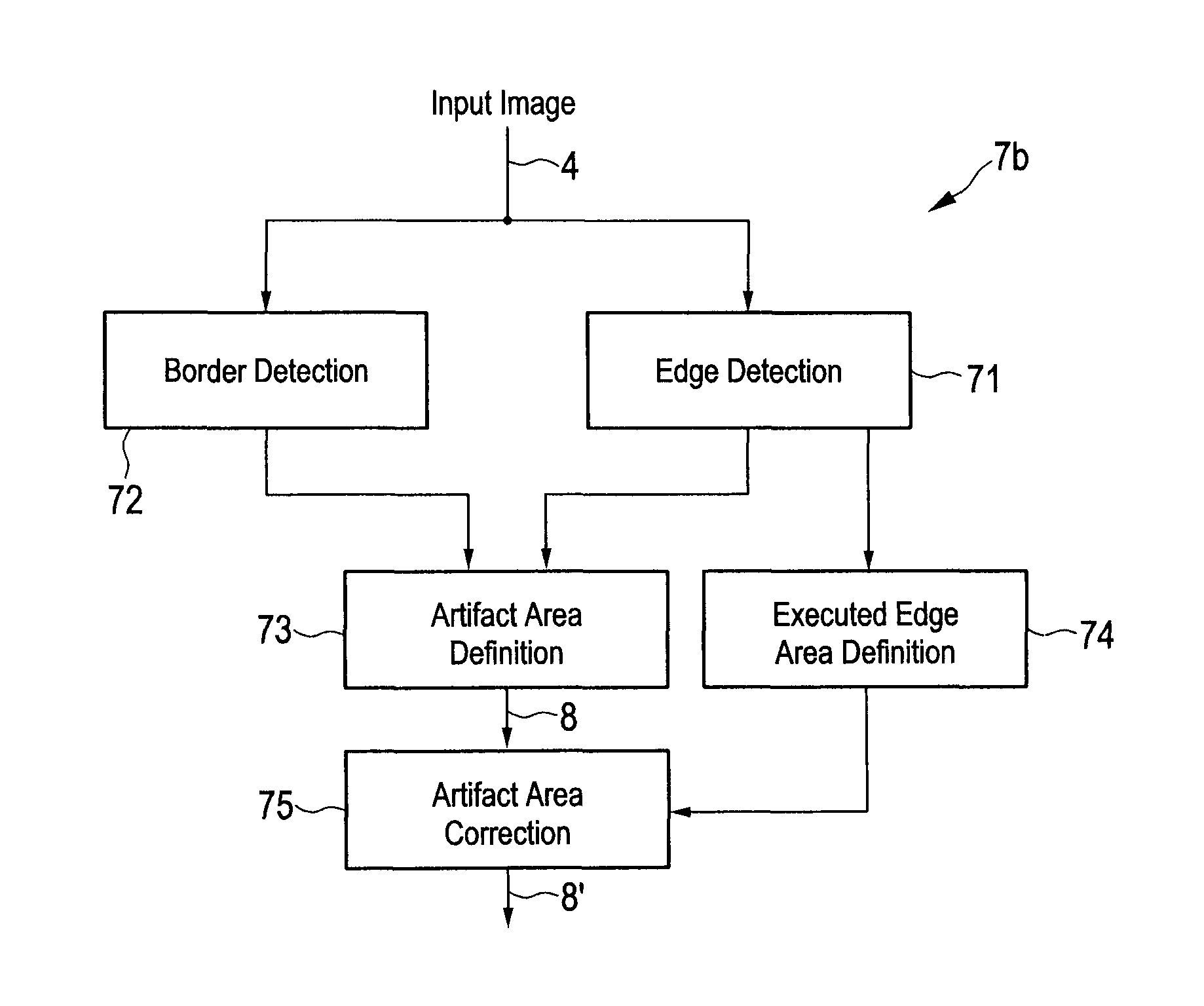
[0053]In a second embodiment illustrated in FIG. 7B said dilated border area is defined 19 by defining a block of a number of dilated border area pixels around the border pixels of the detected border position 14, in particular around each border pixel of the detected border position 14, and by including the dilated border area pixels into said dilated border area 19.

[0054]For the edge detection a known Canny edge detector can be used. The gradient threshold used in this method defines the strength of the edges around that the artifacts shall be detected. In general a high threshold level is prone to miss important edge information, while a low threshold level is prone to have many false positives. While generally a global threshold value can be assigned and used, a threshold level globally and optimally fitting all input material is generally not available. Therefore, the threshold level is generally matched to the quality level of the input material, which can be derived e.g. from...


PUM


Abstract

The present invention relates to a method and a corresponding apparatus for detecting coding artifacts in an image. The proposed apparatus comprises an edge position detector that detects an edge position of an edge in said image, a border position detector that detects a border position of a border between a texture area and a flat area in said image, and an artifact position defining unit that defines the area between said edge position and said border position as artifact area potentially comprising coding artifacts.

Description

CROSS-REFERENCE TO RELATED APPLICATIONS[0001]The present application claims priority of European patent application 10 158 214.6 filed on Mar. 29, 2010.FIELD OF THE INVENTION[0002]The present invention relates to a method and an apparatus for detecting coding artifacts in an image. Further, the present invention relates to a method and an apparatus for reducing coding artifacts in an image. Still further, the present invention relates to a computer program and a computer readable non-transitory medium. Finally, the present invention relates to a device for processing and / or displaying an image.BACKGROUND OF THE INVENTION[0003]The distribution of video content is nowadays not only possible via the traditional broadcast channels (terrestric antenna / satellite / cable), but also via internet or data based services. In both distribution systems the content may suffer a loss of quality due to limited bandwidth and / or storage capacity. Especially in some internet based video services as vide...

Claims


Application Information

Patent Timeline
Patent Type & Authority Patents(United States)
IPC IPC(8): H04N19/136H04N19/86H04N19/176H04N1/32G06K9/42H04N19/182G06K9/46G06T5/00G06K9/44H04N19/17G06K9/62H04N1/41G06K9/40G06T7/00G06K9/66H04N19/117H04N5/00
CPCH04N19/176H04N19/14H04N19/182G06K9/4604G06T7/0091G06T5/002H04N19/86G06T2207/20021H04N19/00909H04N19/17H04N19/114H04N19/117G06T2207/10016G06T7/0081G06T7/0083G06T7/11G06T7/12G06T7/155
Inventor SPRINGER, PAULMOESLE, FRANKLEI, ZHICHUNBRUEGGEMANN, MATTHIAS
Owner SONY CORP
Why Eureka
Try Eureka