Mobile device including a solar battery

a mobile device and solar energy technology, applied in the direction of devices with sensors, optical radiation measurement, navigation instruments, etc., can solve the problems of increased cost, long charging time, user continuously holding the mobile device in his or her hand, etc., and achieve the effect of efficient and appropriate use of inciden

Inactive Publication Date: 2014-11-11
SONY MOBILE COMM INC
View PDF11 Cites 0 Cited by
  • Summary
  • Abstract
  • Description
  • Claims
  • Application Information

AI Technical Summary

Benefits of technology

[0015]On the other hand, the use of the technology disclosed in Japanese Unexamined Patent Application Publication No. 10-239464 makes it possible to detect ambient brightness and also makes it possible to report, to the user, for example, whether or not the current environment is suitable for charging. However, in the case of the technology disclosed in Japanese Unexamined Patent Application Publication No. 10-239464, for example, when the surface of a casing provided with a solar battery panel is shaded or is located at the opposite side of a surface exposed to sunlight, it is determined that the surroundings of the mobile phone is dark in spite of a sufficient amount of sunlight. Thus, even in an environment where charging can be performed to a sufficient level, there is a possibility that this environment is not utilized and the opportunity of charging is lost.
[0018]According to the present invention, since the user can recognize the state of incident light on the light-receiving surface of the solar battery via the output section, it is possible to provide a mobile device that can more efficiently and appropriately use incident light that can be received by the solar battery.

Problems solved by technology

However, since it takes a long time for the charging, the user continuously holding the mobile device in his or her hand is not practical.
With such an approach, however, since a complicated mechanism, such as a posture-control mechanism, is generally necessary, there is a problem of increased cost.
However, in the case of the technology disclosed in Japanese Unexamined Patent Application Publication No. 10-239464, for example, when the surface of a casing provided with a solar battery panel is shaded or is located at the opposite side of a surface exposed to sunlight, it is determined that the surroundings of the mobile phone is dark in spite of a sufficient amount of sunlight.
Thus, even in an environment where charging can be performed to a sufficient level, there is a possibility that this environment is not utilized and the opportunity of charging is lost.

Method used


Image

  • Mobile device including a solar battery
  • Mobile device including a solar battery
  • Mobile device including a solar battery

Examples


first embodiment

Example of Mechanical Structure of Mobile Device

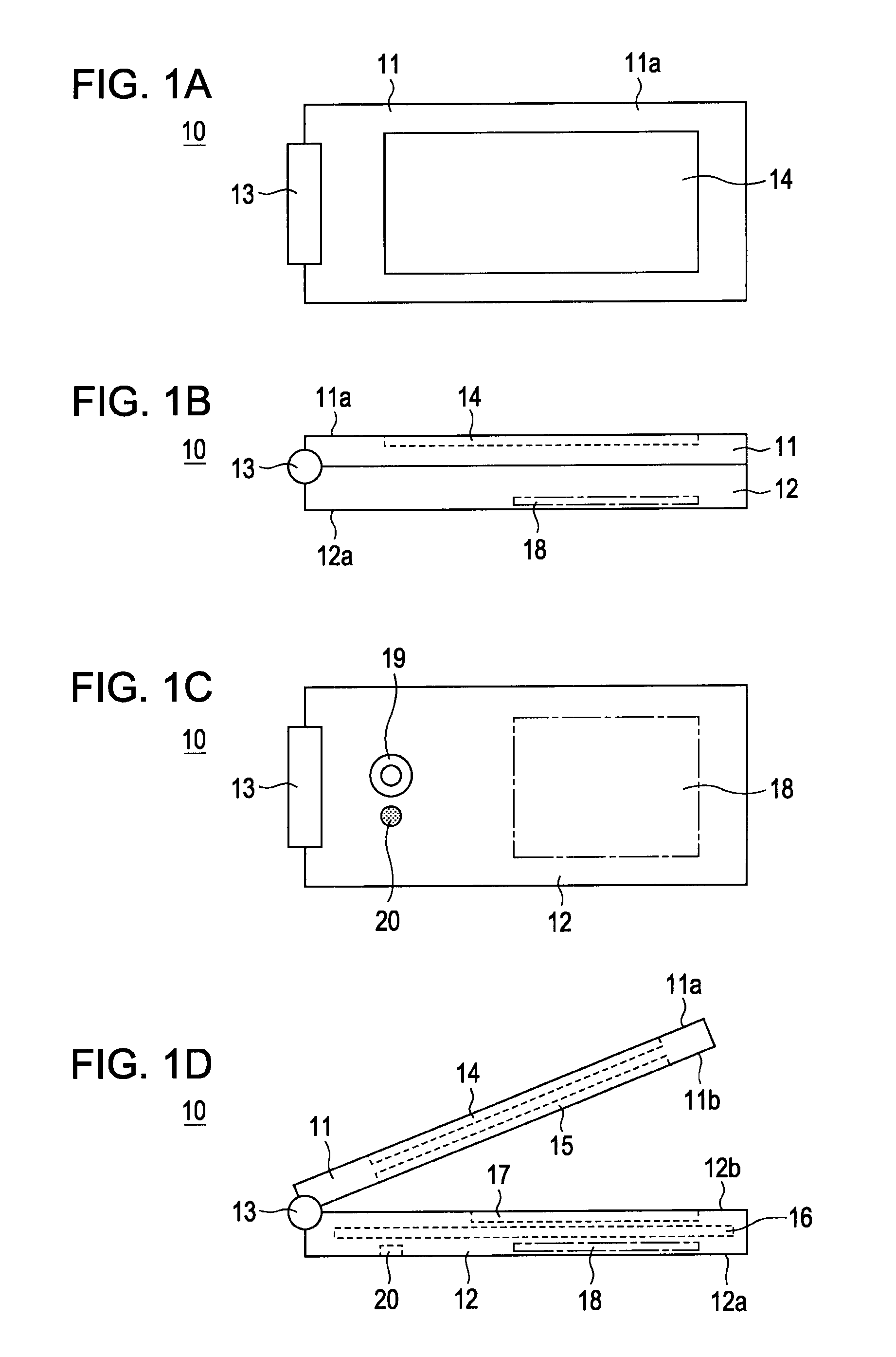
[0039]FIGS. 1A to 1D are schematic external views illustrating a mobile device according to a first embodiment of the present invention. In the present invention, the mobile device may be a mobile phone terminal 10. FIG. 1A is a top view of the mobile phone terminal 10, FIG. 1B is a right side view thereof, and FIG. 1C is a bottom view. The mobile phone terminal 10 in this example is a flip mobile phone. FIG. 1D shows a state in which the mobile phone terminal 10 is slightly opened from a folded state.

[0040]As shown in FIGS. 1A to 1D, the mobile phone terminal 10 has an upper casing 11 and a lower casing 12, which are coupled via a hinge portion 13. The upper casing 11 and the lower casing 12 are configured so that they can be pivoted using the hinge portion 13 as its pivot axis and thus can be opened / closed as shown in FIG. 1D.

[0041]As shown in FIGS. 1A, 1B, and 1D, the upper casing 11 has a solar battery panel 14 and a display device...

second embodiment

[0102]A second embodiment is also directed to an example in which the mobile device is a mobile phone terminal 10 that is similar to the one according to the first embodiment.

[0103]In the first embodiment described above, the illuminance sensor is provided at the surface 12a of the lower casing 12, the surface 12a being located at the opposite side of the surface 11a of the upper casing 11 provided with the solar battery panel 14, to detect the inadequate state in which the solar battery panel 14 is located at the reverse side at which sunlight is not receivable and to report the inadequate state to the user.

[0104]In contrast, according to the second embodiment, illuminance sensors are provided at regions around the solar battery panel 14 at the surface 11a provided with the solar battery panel 14. The illuminance sensors check whether or not the solar battery panel 14 is shaded and reports the result of the checking to the user.

[0105]In the second embodiment, the illuminance sensor...

third embodiment

[0160]FIGS. 15A and 15B show an example of the mechanical structure of a mobile phone terminal 10 according to a third embodiment. The third embodiment is an extended example of the second embodiment. In the case of the second embodiment described above, when sunlight is obliquely incident on the mobile phone terminal 10, there are cases in which the voltage(s) Vd across the LED(s) that serve as the illuminance sensor(s) do not become higher than the threshold voltage Vθ. According to the third embodiment, it is possible to check such sunlight that is obliquely incident.

[0161]FIG. 15A is a top view of the mobile phone terminal 10 according to the third embodiment and FIG. 15B is a cross sectional view taken along line XVB-XVB shown in FIG. 15A. In the third embodiment, the solar battery panel 14 is provided at the surface 11a of the upper casing 11, as in the first embodiment described above, and four LEDs 20A, 20B, 20C, and 20D are provided at four corners of the surface 11a, as in...


PUM


Abstract

A mobile device including a solar battery having a light-receiving surface provided on a casing of the mobile device, an illuminance detector that detects an illuminance of light incident on the casing, an output section that outputs a state of light incident on the light-receiving surface of the solar battery, and a controller that controls the output section based on the illuminance detected by the illuminance detector.

Description

CROSS REFERENCE TO RELATED APPLICATION[0001]This application claims the benefit of priority of Provisional Application Ser. No. 61 / 358,708, filed Jun. 25, 2010, the entire contents of which is incorporated herein by reference.BACKGROUND OF THE INVENTION[0002]1. Field of the Invention[0003]The present invention relates to a mobile device provided with a solar battery.[0004]2. Description of the Related Art[0005]With improvements in the light-to-power conversion efficiencies of solar batteries, mobile devices, such as mobile phone terminals, equipped with solar batteries for energy saving are becoming widely used. Although some of such mobile devices use solar batteries as direct sources for supplying power-supply voltages, many typically have rechargeable batteries that are charged with electrical outputs of the solar batteries.[0006]FIGS. 16 and 17 are diagrams showing examples of the configurations of simplified charging circuits. FIG. 16 shows an example of a simplified charging c...

Claims


Application Information

Patent Timeline
Patent Type & Authority Patents(United States)
IPC IPC(8): H04M1/21H02J7/35H04M1/02G08B5/22
CPCH04M1/21H04M2250/12H02J7/355H02J7/35Y02E10/566H04M1/0214Y02E10/56
Inventor KATO, HIROSHIBENISE, KIMITAKASHIMURA, JUSUKEINOUE, YOSHIAKIHOSODA, YASUHIDE
Owner SONY MOBILE COMM INC
Why Eureka
Try Eureka