
Vehicle control unit and vehicle equipped with the same

a technology of vehicle control and control unit, which is applied in the direction of mechanical equipment, dynamo-electric gear control, instruments, etc., can solve the problems of operator's erroneous operation, transmission, axle or similar breakdown, etc., and achieve satisfactory operation feeling for operator, smooth switch of vehicle traveling direction, and reduction of load applied

Active Publication Date: 2014-11-04
NIPPON YUSOKI
View PDF16 Cites 12 Cited by
  • Summary
  • Abstract
  • Description
  • Claims
  • Application Information

AI Technical Summary

Benefits of technology

The present invention aims to provide a vehicle control unit and vehicle equipped with the unit that can prevent breakdowns and appropriately control vehicle movement by ignoring shifting errors caused by an erroneous operation of the shift lever during traveling modes. This invention aims to reduce complex operations for the driver and ensure safe driving.

Problems solved by technology

However, in a case where the shift operation is erroneously carried out in a direction opposite to a vehicle traveling direction during a vehicle traveling mode, a transmission, an axle, or the like may be broken down by a high shock generated when a transmission gear is engaged in accordance with the erroneous shift operation.
As described above, in a case where the gear of the automatic transmission is erroneously selected by the operator in a direction opposite to the vehicle traveling direction during the vehicle traveling mode at a high speed, the transmission, the axle, or the like may be broken down due to a large shock.
Particularly, in an industrial vehicle represented as a cargo handling machine such as a forklift or a reach stacker and a construction machine such as a motor grader, a bulldozer, or a wheel loader, the forward / reverse switching operation is frequently repeated since the driving operation is carried out in many cases during a work, and thus an operator's erroneous operation may easily occur.

Method used


Image

  • Vehicle control unit and vehicle equipped with the same
  • Vehicle control unit and vehicle equipped with the same
  • Vehicle control unit and vehicle equipped with the same

Examples


Embodiment Construction

[0036]Hereinafter, an exemplary embodiment of the invention will be described in detail with reference to the accompanying drawings. Here, although the dimension, the material, the shape, the relative arrangement, and the like of the component are described in the embodiment, the scope of the invention is not limited thereto so long as a particular description is not made, but those are only examples for a description.

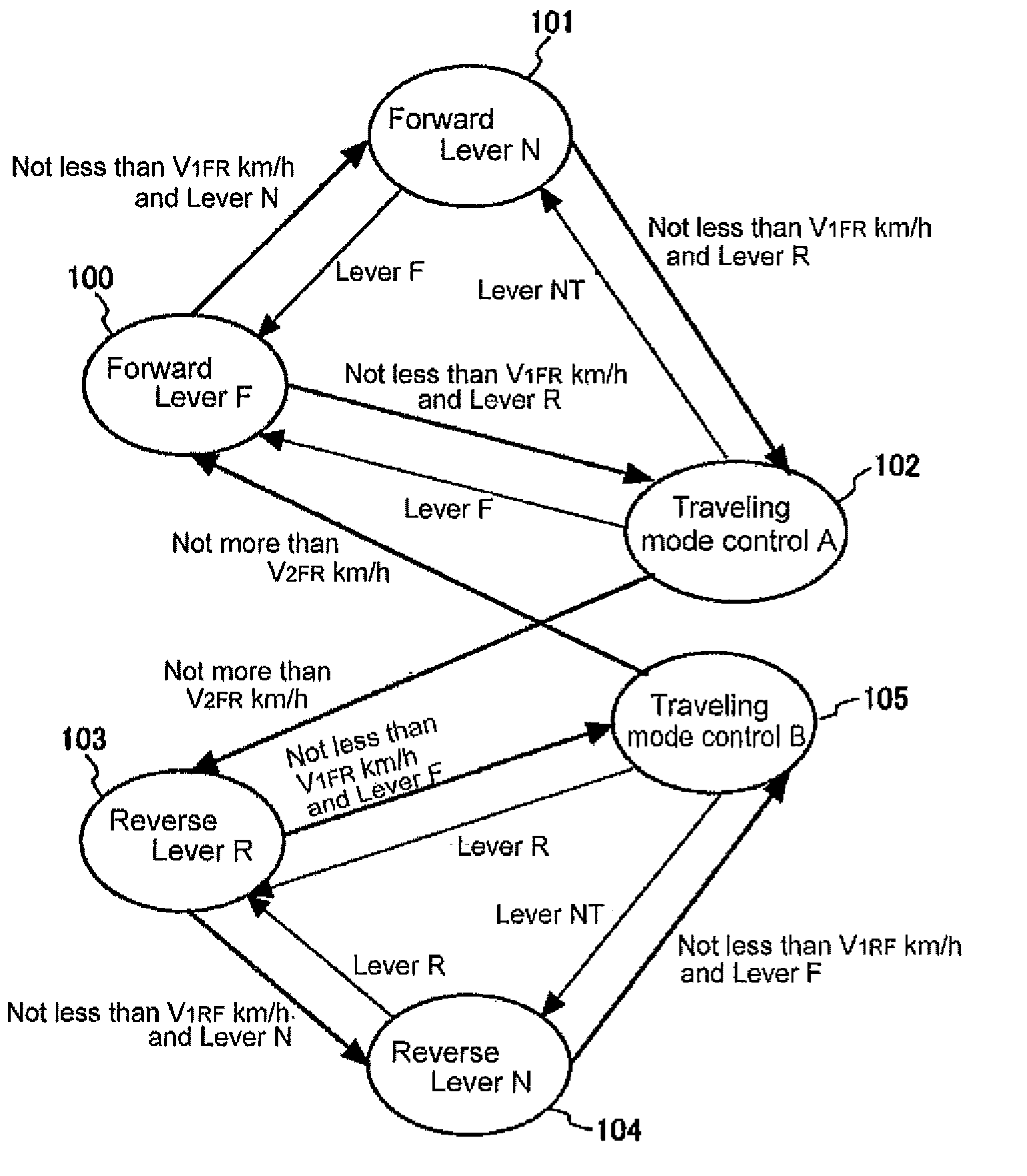
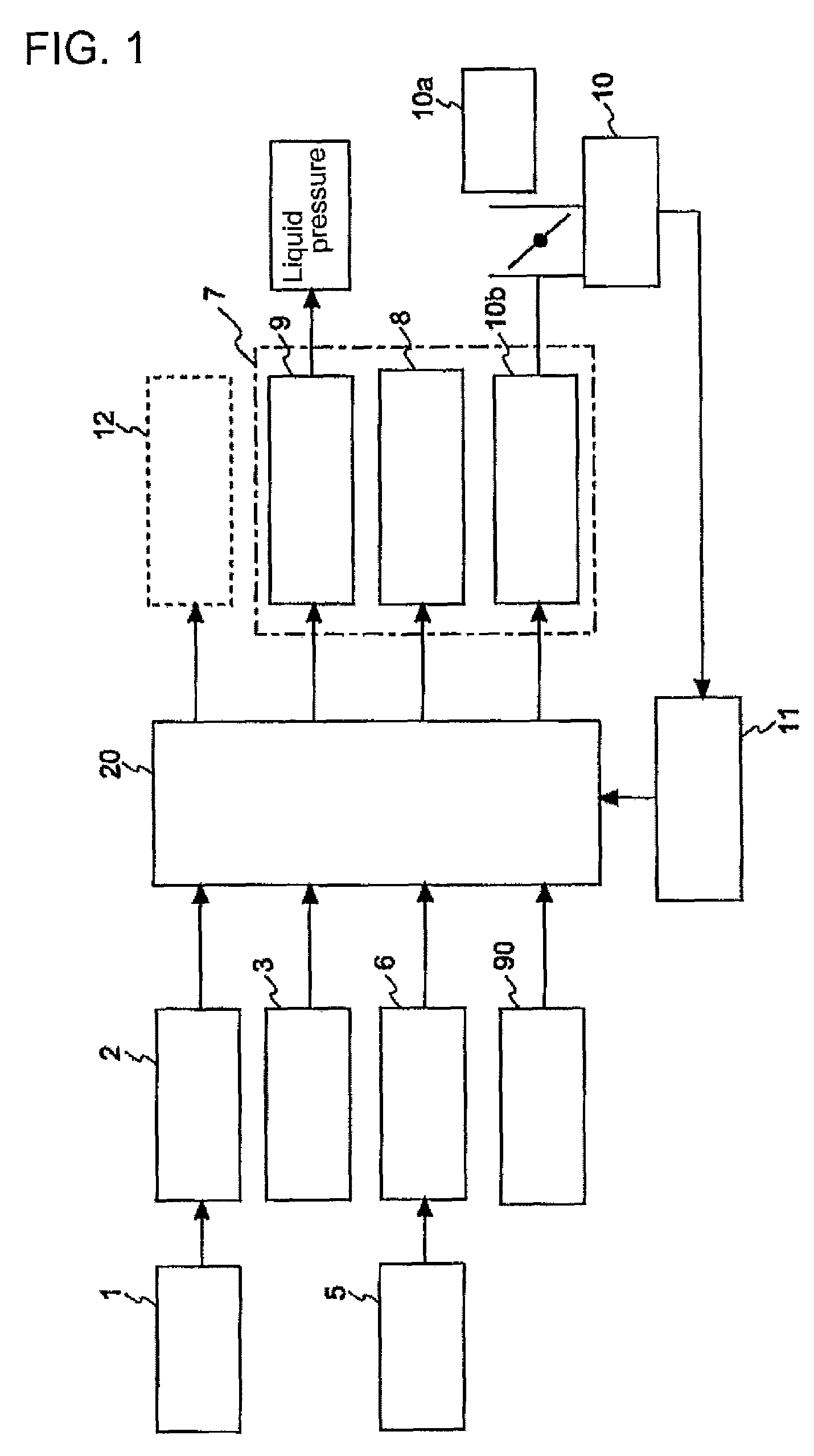
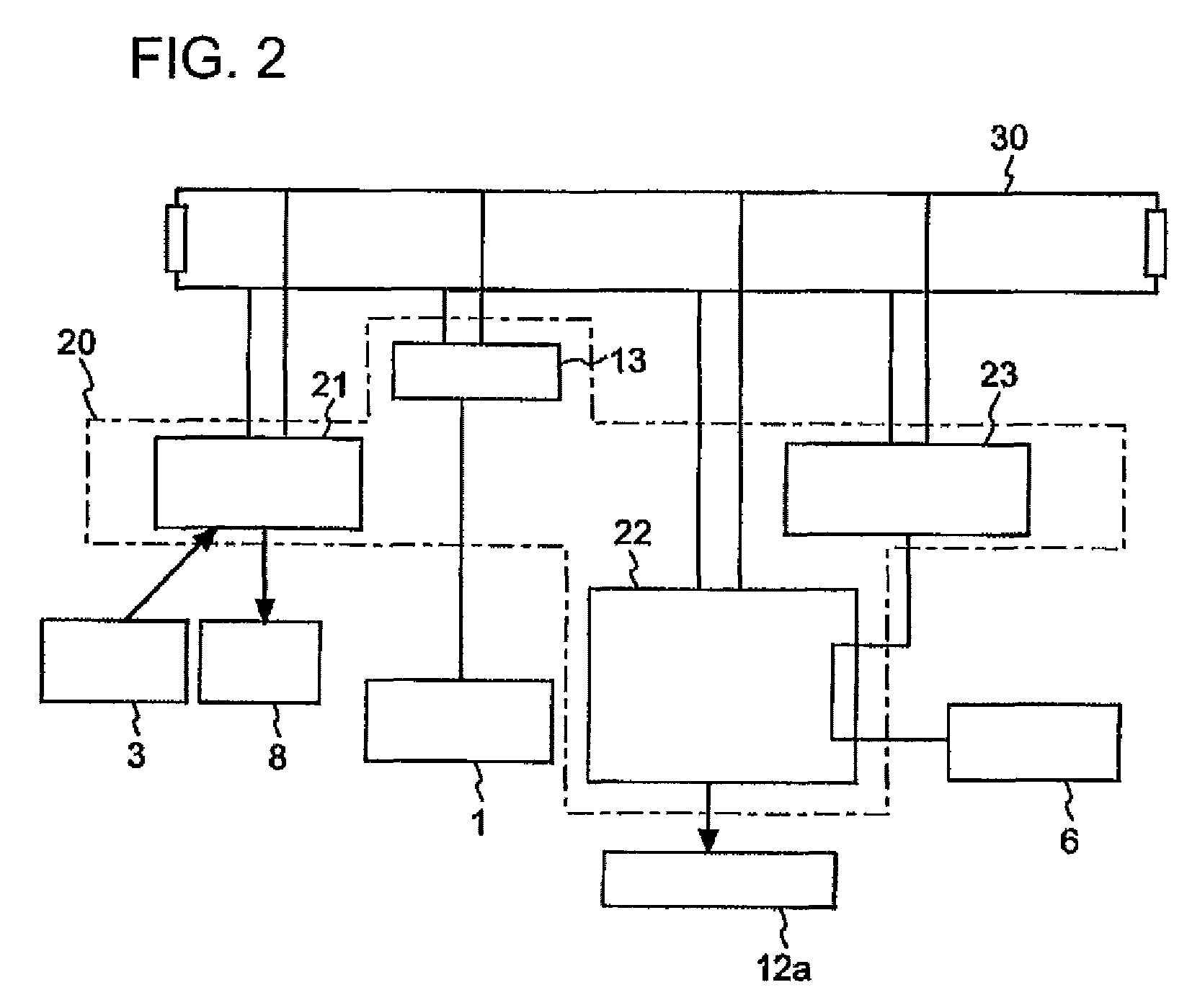
[0037]FIG. 1 is a schematic configuration diagram showing a control unit and peripheral units thereof according to an embodiment of the invention. FIG. 2 is a configuration diagram showing an example of a distributed control unit according to the embodiment of the invention. FIG. 3 is a state transition diagram showing an entire operation of a vehicle equipped with the control unit according to the embodiment of the invention. FIG. 4 is a state transition diagram showing a driving control using the control unit according to the embodiment of the invention.

[0038]In this...


PUM


Abstract

A vehicle control unit and a vehicle equipped with the vehicle control unit are provided, the vehicle control unit being capable of preventing a shift change from being permitted in a direction opposite to a vehicle traveling direction caused by an erroneous operation of a shift lever during a traveling mode. In the vehicle control unit for controlling the vehicle on the basis of a shift range detecting unit configured to detect a shift range selected by a shift operation and a vehicle speed detecting unit configured to detect a vehicle speed, when the shift range detecting unit detects the shift range in a direction opposite to the vehicle traveling direction in a state where the vehicle speed detecting unit detects a vehicle speed not less than a first speed V1, the vehicle control is carried out so that a compulsory deceleration is carried out by means of a deceleration unit provided in the vehicle instead of permitting the shift change corresponding to the shift range, the shift change being desirably permitted when the vehicle speed detecting unit detects that the vehicle speed decreases down to a vehicle speed not more than the first speed V1.

Description

TECHNICAL FIELD[0001]The present invention relates to a vehicle control unit, having a function of preventing a breakdown of a vehicle caused by an operator's erroneous operation during a vehicle traveling mode, and a vehicle equipped with the vehicle control unit, and more particularly, to a vehicle control unit suitable for an industrial vehicle and a vehicle equipped with the vehicle control unit.BACKGROUND ART[0002]Generally, in a vehicle, a driving force of an engine is transmitted to a transmission via a torque converter, and is transmitted to a drive wheel via one of a forward clutch and a reverse clutch received in the transmission, thereby allowing the vehicle to be in a traveling mode. The forward clutch and the reverse clutch are selected by a shift lever used to perform a forward / reverse switching operation.[0003]A control system of a general automatic transmission includes a forward solenoid and a reverse solenoid of an electromagnetic switching valve for controlling a ...

Claims


Application Information

Patent Timeline
Patent Type & Authority Patents(United States)
IPC IPC(8): F16H59/44F16H63/50G06F19/00B60W10/188H02P17/00B60W30/18B60W10/06F16H59/42B60W10/00G06F7/00F16H61/12F16H61/16F16H59/10G06F17/00F16H63/40
CPCF16H2061/165F16H61/16B60W10/06B60W30/18045B60W10/188F16H2312/09Y10T477/33Y10T477/6403
Inventor ISHIKAWA, NAOKIUEDA, KATSUMISEKI, MASANOBU
Owner NIPPON YUSOKI
Learn More