
Pedometer for shoe

a pedometer and shoe technology, applied in the direction of distance measurement, instruments, fastenings, etc., can solve the problems of high manufacturing cost, erroneous measurements, and difficult mounting of piezoelectric transducers and counting devices on the sho

Inactive Publication Date: 2014-11-04
OSHIO KOZO
View PDF44 Cites 27 Cited by
  • Summary
  • Abstract
  • Description
  • Claims
  • Application Information

AI Technical Summary

Problems solved by technology

Therefore, the conventional pedometer may erroneously detect the movement of the body while the user is not walking, which may result in erroneous measurements.
In reality, it is extremely difficult to mount the piezoelectric transducer and the counting device on the shoe.
There is not much space in the shoe to accommodate the piezoelectric transducer and the counting device, the manufacturing cost is very high, the shoe cannot be washed, and the user is required to wear the particular shoe having the step number counting device mounted thereon to measure the number of steps and forced to purchase the same shoe if the shoe wears off.
Although Japanese Utility Model Application Publication No. 05-093209 does not specifically mention the structure of the piezoelectric transducer arranged on the shoe sole, when the piezoelectric transducer, which is made of piezoelectric ceramic, is placed by itself on the shoe sole, the piezoelectric transducer may break due to the loading applied onto the piezoelectric transducer.
A shoe, however, has too severe problems, as discussed below, to accommodate, in the shoe, a pressure sensor, an impulse sensor, an apparatus and a power source to detect movement of the user's foot, and wirings to connect and link the above.
Thus, the invention disclosed in Japanese Patent application Publication No. 2007-300951 is also infeasible, but the publication does not disclose at all how to implement the invention.
When connectors are used to establish connections, the connectors may also lose the contact therebetween, break or suffer from poor connection.
This easily disconnects or degrades the direct connections.
Accordingly, it has been very difficult to dispose wirings in a shoe.
Consequently, it has been extremely difficult to dispose lead wires in a shoe.
Additionally, the space inside a shoe is very dump and humid.
If lead wires are disposed and connected in a shoe, the connections may easily rust and thus degrade.
Therefore, the connections may easily break, be degraded or disconnected as discussed above.
As a consequence, it has been very difficult to arrange and connect wirings in a shoe.
(3) A user wearing a shoe may feel pain and uncomfortable if even a small stone is in the shoe.
It has been thus very difficult to provide, in the shoe, a pressure sensor, and an apparatus and a power source to detect the movement of the user's foot without causing the user to feel uncomfortable.
As discussed above, when a pressure sensor to detect a pressure and an impulse sensor are arranged in a shoe, the number of steps cannot be measured unless the user wears the shoe that already has been modified to have such sensors installed therein.
As seen from Table 1, the conventional in-shoe pedometers also disadvantageously cannot distinguish walking and running and only detect and measure the number of steps.

Method used


Image

  • Pedometer for shoe
  • Pedometer for shoe
  • Pedometer for shoe

Examples


Embodiment Construction

[0078]Hereinafter, some embodiments of the present invention will be described. The embodiments do not limit the invention according to the claims, and all the combinations of the features described in the embodiments are not necessarily essential to means provided by aspects of the invention.

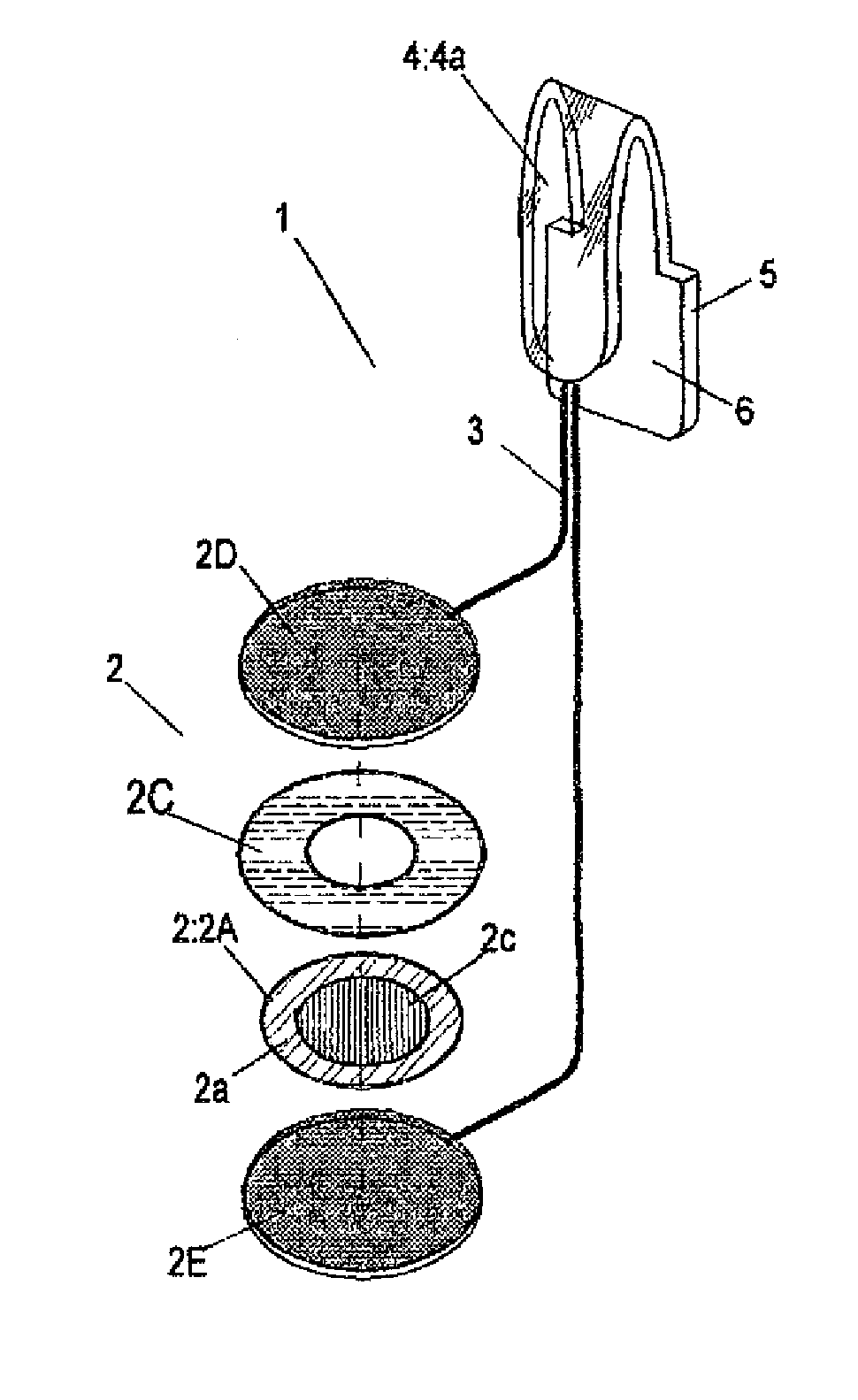
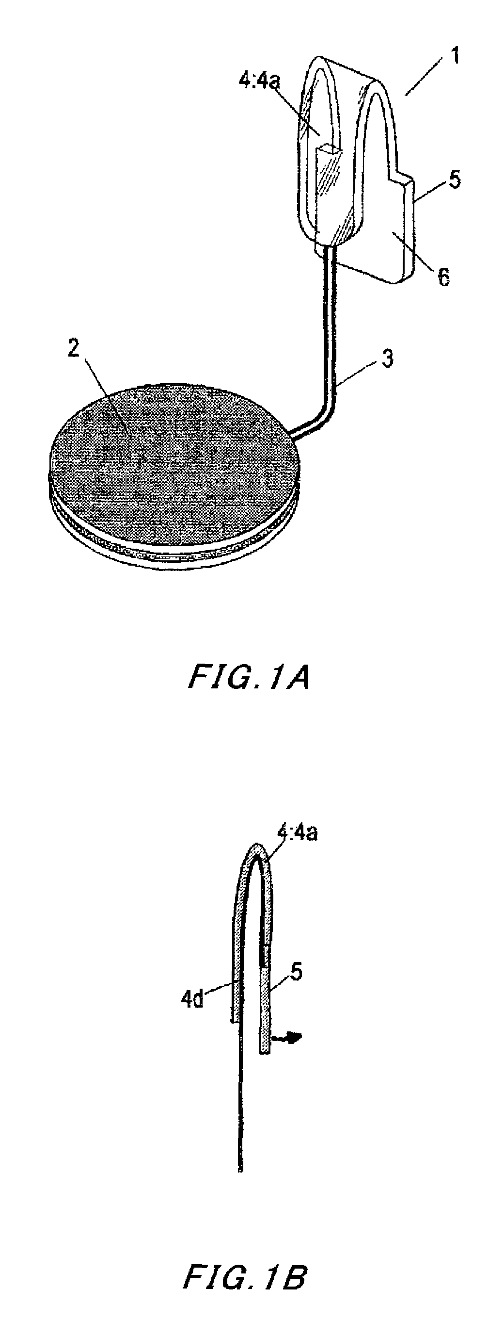
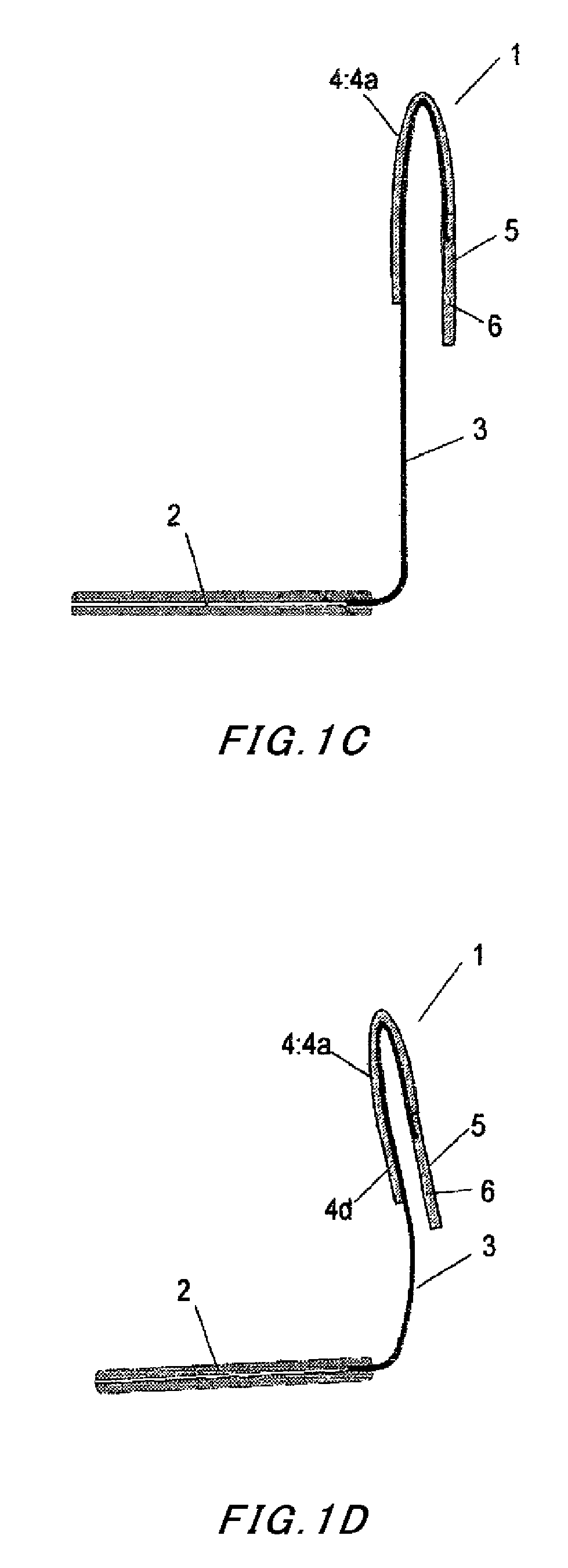
[0079]The following describes in detail exemplary embodiments of the present invention with reference to the attached drawings. FIGS. 1A to 1D and FIGS. 2A to 2D are overall views illustrating exemplary embodiments of the pedometer for a shoe according to the present invention. FIGS. 3A to 3D illustrate exemplary embodiments of an electromotive unit of the pedometer for a shoe according to the present invention.

[0080]Referring to FIGS. 1A to 1D, an electromotive unit 2 is shaped like a flat plate to have a substantially circular outline. A wire material 3 is connected to the electromotive unit 2 and configured to deliver the electric current produced by the electromotive unit 2. The wire materi...


PUM


Abstract

An electromotive unit that produces an electric current in response to a pressure applied thereto when a user lands the ground on his / her foot while walking or running, or a pressure detector that detects variation in the applied pressure is formed like a flat plate and arranged within a small space in a shoe. A wire material is provided to deliver, outside the shoe, the electric current produced in response to the pressure applied when the user lands the ground on his / her foot or a signal indicative of the variation in the applied pressure. The wire material is connected to a pedometer unit outside the shoe to perform counting. The wire material can be fixed and mounted onto a desired portion in the opening of the shoe by using a fastener or by being formed as a fixable wire material.

Description

BACKGROUND[0001]1. Technical Field[0002]The present invention relates to a pedometer for a shoe that is mountable on a ready-made shoe to detect steps during walking and running and to measure the number of walking and running steps.[0003]2. Related Art[0004]In the conventional art, a pedometer has been proposed which can be attached onto a body of a user and measures the number of steps while the user walks by detecting the movement of the body. The movement of the body, however, includes a variety of other ways of movement than walking. Therefore, the conventional pedometer may erroneously detect the movement of the body while the user is not walking, which may result in erroneous measurements. To eliminate such measurement errors, Japanese Utility Model Application Publication No. 05-093209 discloses an invention of measuring the number of steps based on detection of output from a piezoelectric element, for example.[0005]The above-mentioned invention has encountered a problem. Ac...

Claims


Application Information

Patent Timeline
Patent Type & Authority Patents(United States)
IPC IPC(8): A43C19/00G01C21/00G01C22/00A43B3/00
CPCA43B3/0005G01C22/006A43C19/00A43B3/34
Inventor OSHIO, KOZO
Owner OSHIO KOZO
Learn More